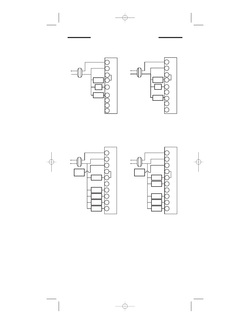
Heat pump with cool active reversing valve, Heat pump + aux cool cool active reversing valve, Heat pump + aux heat heat active reversing valve – Robertshaw 8625-1 User Manual
Page 6: Heat pump with heat active reversing valve, Heat pump wiring diagrams
6
Hot
Compressor
Contactor
Transformer
24 VAC
120 VAC
HEAT PUMP WITH
COOL ACTIVE
REVERSING VALVE
W1
Y1
B
G
O
T
H
E
R
M
O
S
T
A
T
NOTE: Make sure the HP switch is in the HP
position.When switched to HP mode,
W1 is connected internally to Y1.
Reversing
Valve
Fan
Relay
C
R
Y2
W2/E
HEAT PUMP + AUX COOL
COOL ACTIVE
REVERSING VALVE
Hot
Transformer
24 VAC
120 VAC
T
H
E
R
M
O
S
T
A
T
NOTE: Make sure the HP switch is in the HP
position.When switched to HP mode,
W1 is connected internally to Y1.
R
C
L
W1
Y1
B
O
G
Y2
W2/E
Compressor
(24VAC)
Fault Output
Compressor
Contactor
Aux/Emer
Heat
Second
Stage Cool
Fan
Control
Reversing
Valve
Hot
Transformer
24 VAC
120 VAC
HEAT PUMP + AUX HEAT
HEAT ACTIVE
REVERSING VALVE
T
H
E
R
M
O
S
T
A
T
NOTE: Make sure the HP switch is in the HP
position.When switched to HP mode,
W1 is connected internally to Y1.
R
C
L
W1
Y1
B
O
G
Y2
W2/E
Compressor
(24VAC)
Fault Output
Compressor
Contactor
Aux/Emer
Heat
Second
Stage Cool
Fan
Control
Reversing
Valve
Hot
Transformer
24 VAC
120 VAC
HEAT PUMP WITH
HEAT ACTIVE
REVERSING VALVE
W1
T
H
E
R
M
O
S
T
A
T
NOTE: Make sure the HP switch is in the HP
position.When switched to HP mode,
W1 is connected internally to Y1.
Compressor
Contactor
Y1
G
O
B
Reversing
Valve
Fan
Relay
C
R
Y2
W2/E
HEAT PUMP WIRING DIAGRAMS
110-1166 6/8/05 9:15 AM Page 6