Wiring diagrams – Robertshaw 9600 User Manual
Page 11
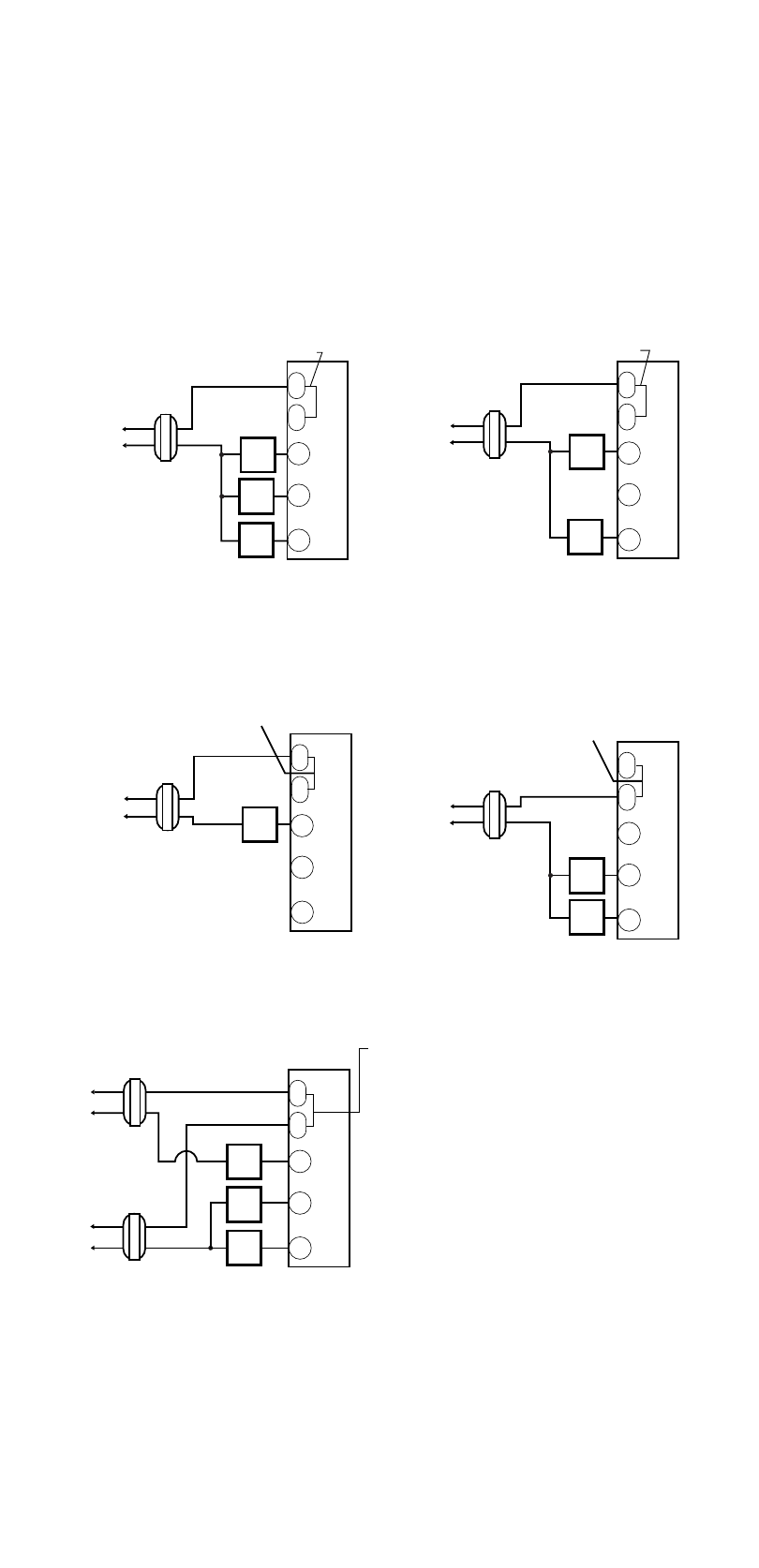
Wiring Diagrams
The following is just a sample of the most common types of HVAC sys-
tems. Refer to your system’s installation manual for wiring information.
11
Hot
Heating
Control
Fan
Control
Cooling
Control
(COOLING)
Transformer
(HEATING)
Transformer
Transformer
T
H
E
R
M
O
S
T
A
T
T
H
E
R
M
O
S
T
A
T
RH
RC
W
Y
G
T
H
E
R
M
O
S
T
A
T
RH
RC
W
Y
G
24 VAC
120 VAC
Hot
Heating
Control
Fan
Control
Transformer
24 VAC
120 VAC
T
H
E
R
M
O
S
T
A
T
RH
RC
W
Y
G
RH
RC
W
Y
G
Hot
Heating
Control
Heating
Control
Transformer
24 VAC
24 VAC
24 VAC
120 VAC
Hot
120 VAC
Hot
120 VAC
HEAT/COOL
4-WIRE
SINGLE TRANSFORMER
HEAT ONLY
2-WIRE
SINGLE TRANSFORMER
HEAT ONLY
3-WIRE
SINGLE TRANSFORMER
Factory-Installed
jumper
Factory-Installed
jumper
T
H
E
R
M
O
S
T
A
T
RH
RC
W
Y
G
Hot
Cooling
Control
Fan
Control
Transformer
24 VAC
120 VAC
COOL ONLY
3-WIRE
SINGLE TRANSFORMER
HEAT/COOL
5-WIRE
TWO TRANSFORMER
CAUTION: Both transformers
must be in phase or damage
to the equipment and thermostat
may result.
Cooling
Control
Fan
Control
NOTE: Cut center of
factory installed jumper
and bend back
NOTE: Remove factory
installed jumper
NOTE: Remove factory
installed jumper