Mounting, Fluid connections, Electrical – Ransburg Aerobell M Rotary Atomizer 78101 User Manual
Page 16: Speed monit
LN-9237-00.1
Aerobell M Rotary Atomizer - Installation
MOUNTING
MOUNTING
MOUNTING
MOUNTING
MOUNTING
The Aerobell M incorporates its own insulator
mounting rod. The diameter at the rear is 1.9
inches, for mounting to a reciprocator, stationary
stand, or other means of support. The atomizer
assembly is mounted to this horizontal rod by a
3/4 inch insulating post, inserted into a swivel
clamp and secured by four plastic bolts. The
arrangement allows positioning of the front of
the turbine. Normally, the insulator support rod
is positioned perpendicular to the conveyor
path, with the swivel providing for left or right
adjustment of the atomizer assembly. The
swivel clamp plate can be inverted to provide a
locking mechanism to hold the applicator in line
with the insulator support rod.
FLUID CONNECTIONS
FLUID CONNECTIONS
FLUID CONNECTIONS
FLUID CONNECTIONS
FLUID CONNECTIONS
The paint supply to the Aerobell M is connected
at the rear of the atomizer assembly to the
regulator. Solvent and dump line connections
enter the housing and are connected to the
appropriate valves. Ports are labeled with blue
lettering.
12
12
12
12
12
>
The normal fluid flow range is 25-500
cc/minute. The maximum flow rate must
not exceed 500 cc/minute to avoid solvent
or paint from flooding into the internal
portion of the air bearing motor assembly
or front shroud.
C A U T I O N
C A U T I O N
C A U T I O N
C A U T I O N
C A U T I O N
!!!!!
ELECTRICAL
ELECTRICAL
ELECTRICAL
ELECTRICAL
ELECTRICAL
CONNECTIONS
CONNECTIONS
CONNECTIONS
CONNECTIONS
CONNECTIONS
Electrical connections to the Aerobell M atom-
izer assembly consist of only the high voltage
cable. This cable plugs into the resistor module
fitting, located at the rear of the assembly, which
protrudes through an opening in the rear bulk-
head. After inserting the cable entirely into the
tube and feeling the banana plug make contact
on the inside, tighten the cable compression
fitting nut around the high voltage cable with an
appropriate wrench. Reinstall the connector
cover with plastic screw.
SPEED MONIT
SPEED MONIT
SPEED MONIT
SPEED MONIT
SPEED MONITOR
OR
OR
OR
OR
CONNECTIONS
CONNECTIONS
CONNECTIONS
CONNECTIONS
CONNECTIONS
A fiber-optic cable assembly connects the
speed signal output of the rotary atomizer
assembly to the Pulsetrak Speed Monitor/
Control System or Fotronics Atomizer Module.
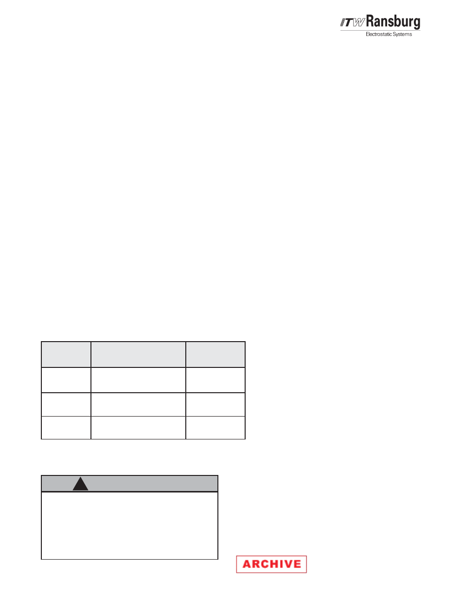
Figure 9: Fluid Tubing Connection Requirements
Figure 9: Fluid Tubing Connection Requirements
Figure 9: Fluid Tubing Connection Requirements
Figure 9: Fluid Tubing Connection Requirements
Figure 9: Fluid Tubing Connection Requirements
.156", .170", or .188" I.D.
PFA, Teflon
.125" I.D.
PFA, Teflon
.250" I.D.
PFA, Teflon
Paint Line
(P.IN)
Solvent Line
(SOL)
Dump Line
(DUMP)
100 psig
(689 kPa)
30-60 psig
(207-413 kPa)
Variable
Fixed
Fixed
Fixed
Fixed
Fixed
Atomizer
Atomizer
Atomizer
Atomizer
Atomizer
Pressure
Pressure
Pressure
Pressure
Pressure
(nominal/max.)