Archive, Rem automatic applicator - maintenance – Ransburg REM Automatic Applicator 73499 User Manual
Page 28
AA-87-02.3
2 3
2 3
2 3
2 3
2 3
REM Automatic Applicator - Maintenance
2. Push front u-cup seal [9] on the needle shaft
[11] with the dished outside to the front of the needle
shaft [11].
3. Place spreader seal [8] on needle shaft [11]
with flatest side toward the front of the needle shaft
[11].
4. Place jam nut [7A] on the threads of the needle
shaft [11] and tighten until it reaches the bottom of
the threads. Place ball valve needle [7] on shaft
and finger tighten it until the threads bottom out.
then with the two 2.5mm wrenches, tighten the
jam nut [7A] against the ball valve neelde [7].
>
Apply a heavy coating of dielectric
grease to the seals.
N O T E
N O T E
N O T E
N O T E
N O T E
5. Insert the valve seal [6] and valve seat body
[5] into the front of the barrel [18], chamber [102]
and tighten snuggly.
6. Coat the plastic portion of the needle shaft [11]
with dielectric grease and slide the packing tube
[12] over the plastic portion of the needle shaft
[11].
7. Slide the rear seal container [13], with the o-
ring gland on the outside, toward the front of the
needle shaft [11].
8. Install the o-ring [13A] onto the outside of the
rear seal container [13].
9. Carefully put rear u-cup seal [14] with the o-
ring to the rear of the needle shaft [11].
10. Put the rear seal retainer [15] onto the needle
shaft [11]. Grease the full assembly.
11. Place the packing nut [16] on the rear threads
of the needle shaft [11]. Insert the full assembly
into the barrel [103] and tighten Item 16 with the
spanner wrench.
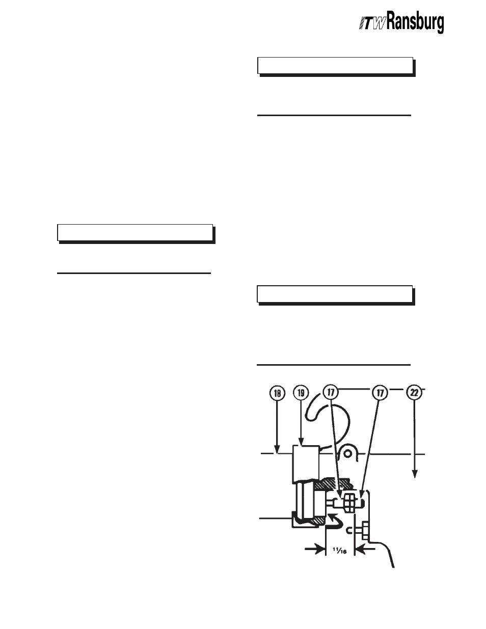
12. Screw the trigger adjusting nut [17] and
extension valve rod [22] onto shaft [11] with the
hexagonal flange or nut facing each other.
13. To adjust nuts [17]:
a. Push needle shaft assembly [11] fully
forward until ball end [7] on shaft [11] seats
in valve seat [5].
b. Measure 11/18-inch from rear lip of barrel/
cascade chamber [103] to the rear face of
the hexagonal flange of the nut on the
extension rod [22].
>
The packing nut should be just tight
enough that shaft [11] slides in and out
with firm resistance.
N O T E
N O T E
N O T E
N O T E
N O T E
>
The 11/16-inch dimension is a starting
point. Because of component stack-up,
wear and other variables, a slight in-
crease or decrease in this setting may be
needed.
N O T E
N O T E
N O T E
N O T E
N O T E
Figure 1: Nut Adjustment
Figure 1: Nut Adjustment
Figure 1: Nut Adjustment
Figure 1: Nut Adjustment
Figure 1: Nut Adjustment
ARCHIVE