9060 fuse replacement, Ransburg – Ransburg No. 2 Process Handgun Electric Motor User Manual
Page 40
No. 2 Process Electric Motor Version - Maintenance
Ransburg
36
AH-13-01.1
DO NOT apply dielectric grease or any
other lubricant to the PTFE seal (Item 8), ce-
ramic seal (Item 5), drive shaft (Item 7), or
collar (Item 1). The application of dielectric
grease or any other lubricant to these com-
ponents can cause premature failure of the
motor.
10. Place the nut (Item 3) onto drive shaft (Item
7) side with threads toward ceramic seal (Item
5). Slide it back on drive shaft as far as it will go.
11. Slip the collar (Item 1) onto the drive shaft
(Item 7), align the two set screws with the two
flats in drive shaft. Secure the collar to the drive
shaft by tightening the two set screws (Item 2).
12. Install the outer O-ring (Item 6) on the drive
shaft.
13. Install the resistor (black ink end first) and
spring into the rear of the drive shaft (Item 7).
Spring must be long enough to contact end of
resistor and motor shaft.
14. Holding the gun assembly with the front of the
barrel angled slightly downward, slide the drive
shaft (Item 7) into the front of the barrel until it
bottoms. Rotate the drive shaft by hand until you
feel the slot engage the motor shaft pin. Tighten
nut (Item 3) to secure the drive shaft to the gun
assembly.
If the nut will not thread fully, the shaft is
not engaged. Unscrew and repeat Step 13.
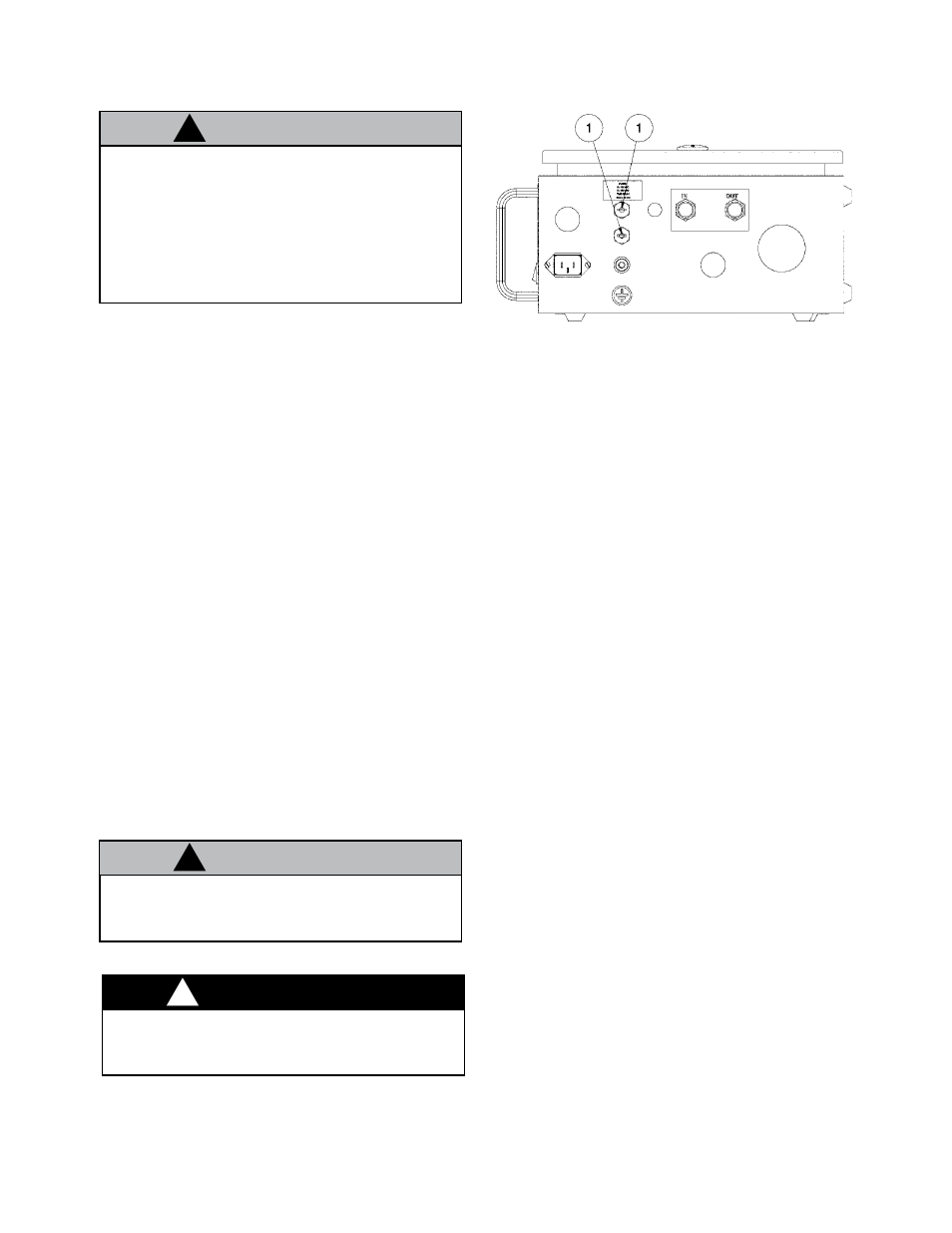
9060 FUSE REPLACEMENT
When ever the 9060 power supply is ser-
viced, insure that the power is off to the unit.
1. Insure the power is turned off on the front
panel switch. If possible disconnect the line cord
to the unit.
2. Insert a flat bladed screwdriver into the slot of
the fuse holder. Push the end of the fuse holder
in and turn counter-clock wise to remove the fuse.
3. Inspect the fuse, insure it is the proper fuse
to give the proper protection. If faulty, replace as
required. Extra fuses are supplied with the 9060
and located inside the lid of the supply.
4. Insert the end of the fuse holder back with the
fuse in the center and push down while turning the
holder 1/4 turn clock-wise to lock back in place.
Figure 25: Fuse Location
C A U T I O N
!
C A U T I O N
!
W A R N I N G
!