Gun electrical output, Ransburg – Ransburg No. 2 Process Handgun Electric Motor User Manual
Page 24
No. 2 Process Electric Motor Version - Operation
Ransburg
20
AH-13-01.1
NOTE
W A R N I N G
!
and remove the bell from the gun by following the
steps outlined under “Shutdown” in the “Opera-
tion” section.
Paints and solvents MUST ONLY be
flushed into earth grounded metal safety
containers.
4. Reposition the feed tube to the five o’clock posi-
tion and trigger the gun into a grounded container
until there is no evidence of paint in the stream.
5. Release the trigger and remove the feed tube.
Wipe the feed tube thoroughly. Pull trigger to flush
material trapped by feed tube o-ring.
Keep the barrel of the applicator angled
downward until the solvent is completely
drained out of it.
6. Release the trigger, replace the gun on the
stand, and release the fluid pressure. Reinstall
the feed tube. Feed tube o-ring may swell from
solvent and need regular replacement.
7. Connect the gun to the new paint supply, set
for normal operation, and apply pressure.
8. Trigger the gun for a few seconds to remove all
of the solvent from it and the hose (until paint flows
from feed tube). Replace the bell and reposition
the feed tube.
9. Turn the gun motor and high voltage switch ON
and resume normal operation.
GUN ELECTRICAL
OUTPUT
Because the high voltage output of the No. 2
handgun affects the coating material atomization
and the efficiency of the application, it is important
to ensure that the electrical portion of the system
is operating correctly. This can be accomplished
by performing a Short Circuit Current Test (SCI).
The normal SCI reading should be between 80 to
115 microamperes (.08 to .115 milliamperes). See
“Gun Output Test” in the “Maintenance” section.
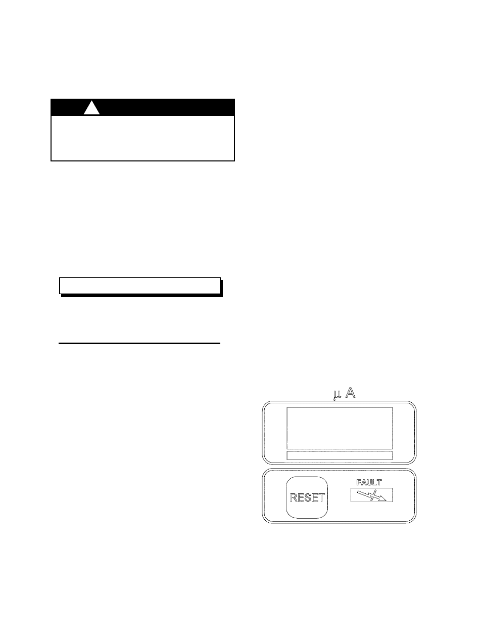
Power Supply Microampmeter
The power supply, used with the 19372 –AAU No.
2 Handgun, is equipped with a microampmeter,
that can be used to indicate the total collective
current demand for the system (i.e., power supply,
handgun, fluid line, and paint and target distance).
Under normal operating conditions the meter
should indicate between 5 and 50 microamperes
(.005 to .05 milliamperes). Readings outside the
range may indicate a possible paint resistance
and/or target distance problem, or component
failure. See the “Troubleshooting Guide”, the
“Gun Output Test”, or the “Gun Short Circuit
Current Test” in the “Maintenance” section for
troubleshooting procedures.
Figure 13: 9060 Micro Amp Meter