Fluid fitting installation procedure, Installation feed tube, bell, brush, Ransburg – Ransburg No. 2 Process Handgun Electric Motor User Manual
Page 16
No. 2 Process Electric Motor Version - Installation
Ransburg
12
AH-13-01.1
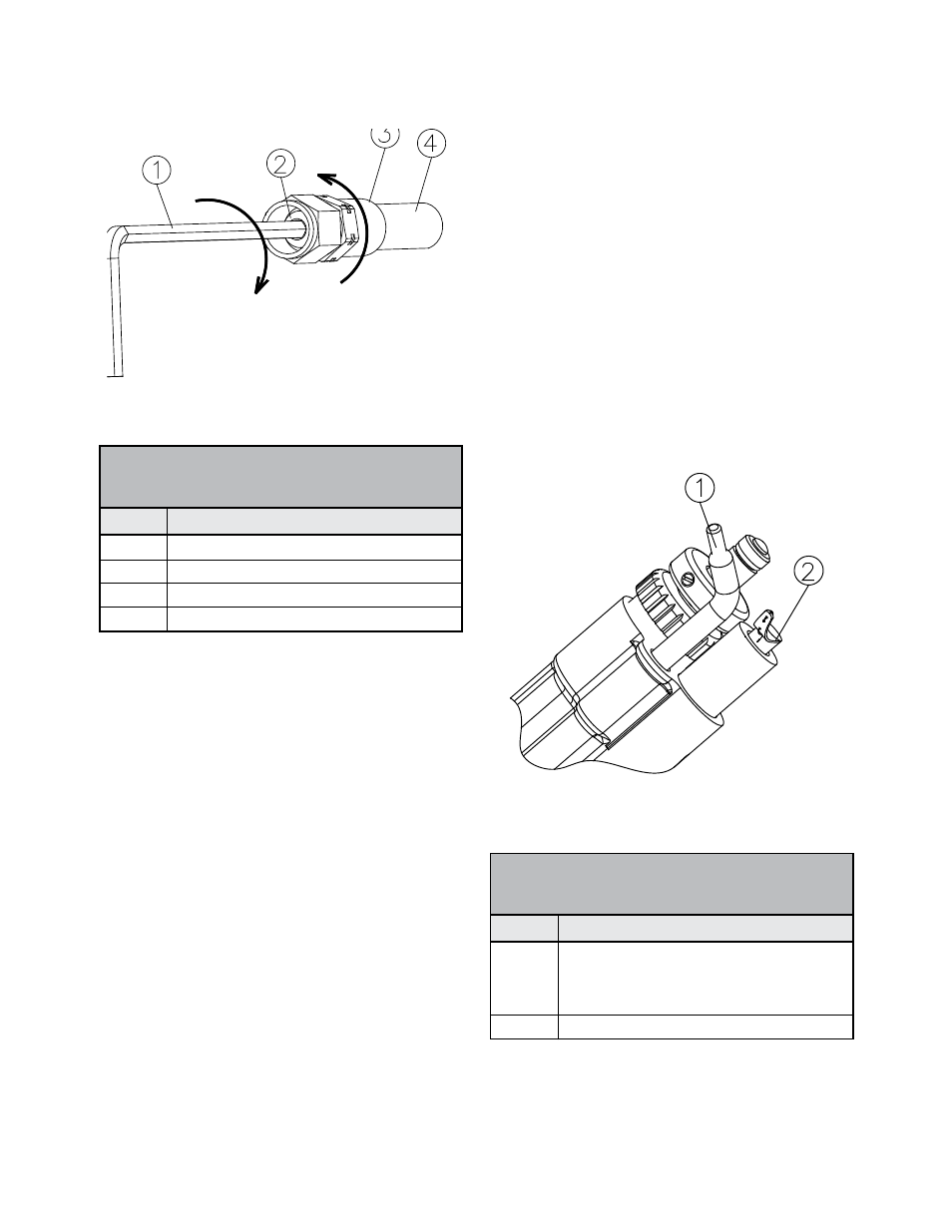
Figure 5: Fluid Fitting Assembly Procedure
FLUID FITTING
INSTALLATION
PROCEDURE
1. Lubricate all fittings with dielectric grease.
2. Screw ferrule (item 3) counterclockwise onto
hose (item 4) until it bottoms, then back it off ap-
proximately 3.2 mm (1/8”).
3. Install nut over union stem and start the stem
into the hose.
4. Using a 4.5 mm hex key (3/16-inch ), screw
the union stem into the hose until it bottoms
against the ferrule.
INSTALLATION FEED
TUBE, BELL, BRUSH
1. Install the proper feed tube into the opening in
the applicator. See figure 6. Position the tube at
approximately as shown in the figure.
2. Insert the 3695-00 (item 2) brush into the bar-
rel. Position it as shown in figure 6.
3. Install the bell over the shaft. Hold the shaft of
the applicator and rotate the bell onto the shaft
until the bell is completely seated. Align the set
screw and the flat on the shaft. Tighten the set
screw at the bell hub hand tight. (Refer to Figure 7)
Figure 6: Initial Position of Feed Tube
and Brush
Item #
1
2
3
4
FLUID FITTING ASSEMBLY
PROCEDURE
(Figure 5)
Description
4.5 mm (3/16”) Hex Key
Stem
Ferrule
Hose, Fluid
Item #
1
2
INITIAL POSITION OF FEED
TUBE AND BRUSH
(Figure 6)
Description
Feed Tube 3700-00 for 4” Bell
Feed Tube 6335-00 for 2 3/4” Bell
Feed Tube 4076-00 for 6” Bell
3695-00 Brush