Accessory installation, Ransburg, Installing bell on shaft – Ransburg No. 2 Process Handgun Electric Motor User Manual
Page 17: Bell cleaning can gun holder
No. 2 Process Electric Motor Version - Installation
Ransburg
13
AH-13-01.1
Figure 7: Installing Bell
on Shaft
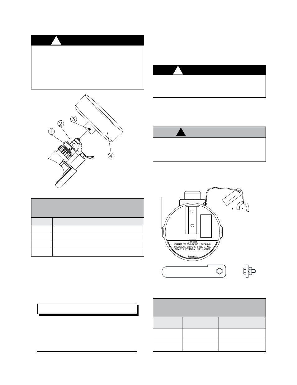
4. Re-position the feed tube in the bell cavity at
approximately the 4 to 5 o’clock position. The
feed tube should NOT rub on the bell. Adjust the
feed tube if necessary, by rotating it or sliding it
forward or backward in the barrel.
The bell and feed tube MUST be
matched to ensure proper fluid feed into
the bell cavity. The following chart will as-
sist in selecting the proper bell and feed
tube combination:
Figure 8: Bell Cleaning Can and Gun Holder
Bell Cup Cleaning
Can 5170
Gun Holder 3936
NOTE
The Bell Cleaning Can provides a convenient and
portable method of removing excess materials
from the bell cup at the conclusion of spray.
Item #
1
2
3
4
INSTALLING BELL ON SHAFT
(Figure 7)
Description
No. 2 Motor Shaft
Shaft Locating Flat
Bell Set Screw
Bell
Bell Size
2 3/4 “
4”
6”
BELL CLEANING CAN GUN
HOLDER
(Figure 8)
Feed Tube #
6335-00
3700-00
4076-00
Position of Tube
@2 o’clock
@4-5 o’clock
@4-5 o’clock
W A R N I N G
!
Insure ground line of the bell cleaning can
is attached to true earth ground when either
solvent is stored in the can or the can in use.
W A R N I N G
!
Replacing the plastic set screw with one
of conductive material (metal) will cause a
hazardous condition to exist, capable of pro-
ducing an electrical discharge possible of
sparking a fire. In all cases use the plastic
screw provided or provided as a spare part.
Insure any cleaning solvent used meets
criteria listed in the maintenance section of
this manual.
C A U T I O N
!
The gun holder provides a method to mount and
store the applicator when not in use.
ACCESSORY INSTALLATION
Included with the unit are two accessory items:
• Bell cleaning can and the gun holder.