Sp10 assembly, installation and operation – Finish Thompson SP10 SERIES SELF-PRIMING User Manual
Page 5
5
Maximum Allowable Motor Power
• Do not exceed the maximum power rating for the pump coupling.
• Standard coupling for the SP10 is 10-pole & maximum 2 HP (1.5 kW).
Priming Liquid Volume
Initial filling (or refilling after maintenance) of the pump housing requires 0.6 US gallon / 77 oz. (2.7 liters) of liquid.
Unpacking and Inspection
Unpack the pump and examine for any signs of shipping damage. If damage is detected, save the packaging and notify the carrier
immediately.
Section I - Assembly
Tools Required:
Metric socket or wrench set, 9/16” socket or wrench, 8 mm
Allen wrench, and 3/16” Allen wrench (NEMA motors
only) and pliers (for fill/drain plugs).
Pumps with Motors
Proceed to “Installation” Section II.
Pumps Without Motors
1. Remove the pump, drive magnet assembly and hard-
ware package from the carton.
CAUTION: Keep away from metallic particles, tools
and electronics. Drive magnets MUST be free of metal
chips.
WARNING
: Keep the drive magnet away from the
open end of the motor adapter and barrier. Strong mag-
netic attraction could allow the drive hub to enter the
motor adapter resulting in injury or damage.
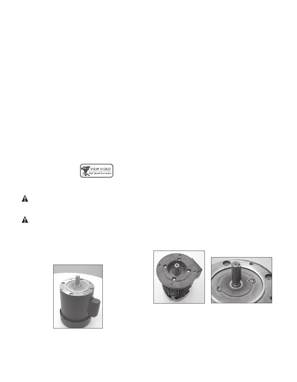
2. Place motor on the fan end. See figure 1.
NOTE: For 56C/145TC frame motors go to step 4.
Figure 1
3. For Metric motors install the motor adapter flange
(item18) on the motor face using bolts, lock washers
and flat washers (items 31,32 & 33). See figure 2.
Torque bolts to the following:
• 63 frame (M4) = 30 in-lb (3.4 N-m)
• 71 frame (M5) = 90 in-lb (10.2 N-m)
• 80 frame (M6) = 90 in-lb (10.2 N-m)
NOTE: 63/71 B14 adapter flange is reversible. Install
63/71 B14 adapter so that proper motor flange size is
facing motor.
NOTE: Apply anti-seize compound on the threads of
the bolts.
4. Coat the motor shaft with anti-seize compound. Insert
the key supplied with the motor into the keway on the
motor shaft. See figure 3.
Note: Make sure the motor shaft is clean & free of
burrs. The outer drive is precision machined and has a
bore tolerance of +.0005/-0 inch.
Figure 2
Figure 3
SP10 Assembly, Installation and Operation