Finish Thompson SP10 SERIES SELF-PRIMING User Manual
Page 12
12
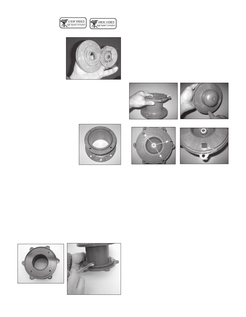
Impeller Replacement
To remove the impeller from the inner drive magnet, gently
pry off by hand or lightly
tap on the back of the im-
peller. See figure 28.
To install a new impel-
ler, place the inner drive
magnet assembly face up.
Line up the patterns on the
impeller with the ones on
the inner drive magnet so
they match and press into place by hand. An arbor press can
also be used to press the impeller on the inner drive. Place
a piece of wood over the top of the impeller thrust ring and
push down on the impeller until it is completely seated in
the inner drive.
Figure 28
Section VI Reassembly
1. Place motor adapter (item 15)
so the large flange is on the
bench. Rotate the adapter so
the four holes in the smaller
flange are in the horizontal
position. See figure 29. If re-
moved, reinstall the o-ring
(item 14) in the groove on the
face of the motor adapter.
Lubricate the o-ring with chemically compatible lubri-
cant. This will help to hold it in place. See figure 29.
Figure 29
2. Install clamp ring. Note: The discharge fitting must
be in the vertical position for all SP series pumps to
work properly – Install the clamp ring (item 13) on the
motor adapter so NO clamp ring bolt holes are in 12:00
or 6:00 position (see figure 30). Align the (4) bolt holes
with the bolt holes in the motor adapter & push straight
down. This will properly seat the o-ring to prevent
vapors from entering this area during pump operation.
3. Install (4) flat washers, lock washers and M8 bolts
(items 22, 23, 24). Tighten evenly using a star pattern.
Tighten to 60 in-lbs (6.8 N-m). See figure 31.
Figure 30
Figure 31
4. Install barrier into motor adapter/clamp ring assembly.
NOTE: If removed, reinstall the o-ring (item 12), lubri-
cate with a chemically compatible lubricant, and install
in the groove in the clamp ring before installing the
barrier. See figure 33A. Lubricate the back of the bar-
rier with a chemically compatible lubricant and push it
straight down into place. See figure 33B. Note: Barrier
can only be installed in one position. The barrier prongs
should be placed in the 11:00, 2:00 and 5:00 o’clock
positions. See figure 33 for correct orientation. Line up
the 5:00 o’clock prong with the bottom bolt hole in the
motor adapter. See figure 33C.
Figure 33A
Figure 33B
Figure 33
Figure 33C
5. Install o-ring (item 4) in groove in the barrier making
sure it is tucked in all the way around.
6. Install impeller shaft (item 10) into barrier by aligning
the flats on the shaft with the ones in the barrier. Make
sure it is completely seated.
7. Carefully install the impeller/inner drive assembly
(items 8, 8A, 9 & 9A) by sliding it over the impeller
shaft in the barrier. It is normal for the impeller/inner
drive to pop up a slight amount due to magnetic forces
with the metal clamp ring. See figures 34 & 35.