Finish Thompson DB3, 4, 5 & 5.5 Series User Manual
Page 9
wear protective clothing, eye protection and follow standard
safety procedures when handling corrosive or personally harmful
materials . Proper procedures should be followed for draining and
decontaminating the pump before disassembly and inspection of
the pump . There may be small quantities of chemicals present
during inspection .
WARNING: Magnetic force hazard . This pump should only
be disassembled and assembled using the recommended proce-
dures . The magnetic attraction is powerful enough to rapidly pull
the motor end and the wet end together . To avoid injuries, do not
place fingers between the mating surfaces of the motor and wet
end . Keep the drive magnet and impeller assembly away from
metal chips or particles .
1 . Stop the pump, lock out the motor starter, close all the
valves that are connected to the pump, and drain/decon-
taminate the pump .
WARNING: The pump must be thoroughly flushed of any
hazardous materials and all internal pressure relieved prior
to opening the pump . Allow the pump to reach ambient
temperatures prior to performing maintenance .
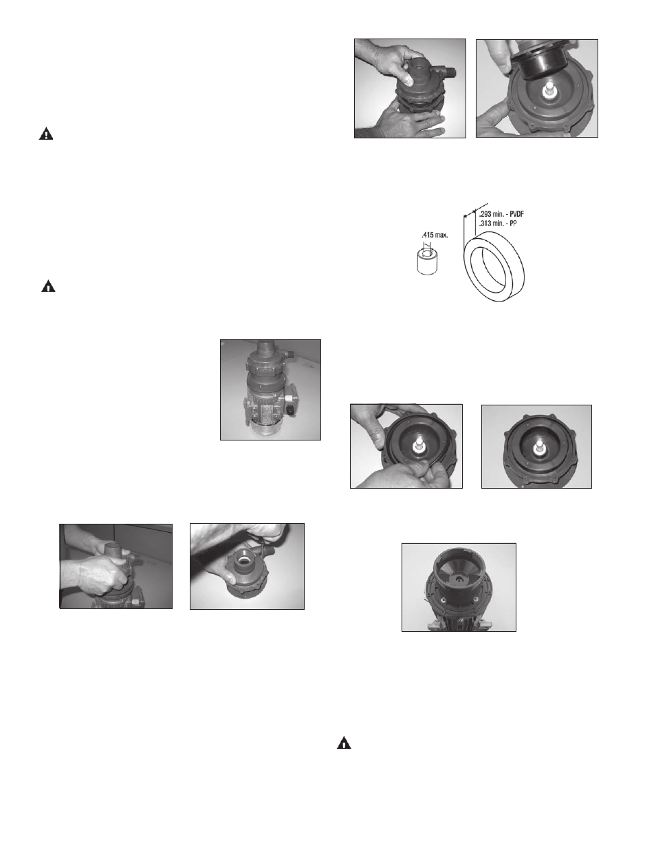
2 . Place the pump & motor vertically
on the motor fan end on a work
bench . Remove the (4) screws (item
8) securing the pump to the motor
adapter / barrier (item 4) . See
figure 13 .
Figure 13
3 . Firmly grab the pump and pull straight up to disengage the
motor and pump . See figure 14 .
4 . Place pump on bench with housing facing up . Remove (8)
housing screws (item 7) . See figure 15 .
Figure 14
Figure 15
5 . Pull housing (item 1) straight up to remove . Inspect hous-
ing for signs of wear or damage . Look for signs of rubbing or
cracked thrust ring . See figure 16 .
6 . Remove impeller assembly (item 3) . See figure 17 . Inspect
impeller and drive for signs of wear or damage . Look for
signs of rubbing, damage and wear . Check the impeller
thrust ring and bushing for wear .
NOTE: Replace the thrust washer and bushing if wear ex-
ceeds dimensions in figure 18 .
Figure 16
Figure 17
Figure 18
7 . Remove the o-ring (item 2) and look for chemical attack,
swelling, brittleness, cuts, etc . See figure 19 .
8 . Inspect the motor adapter / barrier (item 4) . Inspect the
inside and outside for signs of rubbing or damage . See
figure 20 .
Figure 19
Figure 20
9 . Visually inspect the outer drive (item 5) for rubbing, damage,
corrosion or loose magnets . See figure 21 .
Figure 21
Outer Drive Replacement
1 . Remove the bolt, lock washer and flat washer (items 9,10 &
11) from the center of the drive . Hold the drive with your
hand to prevent it from turning . See figure 22 .
WARNING: Be careful, tools may be attracted to the magnets .
2 . Remove the drive magnet from the motor shaft by gently
pushing down on 2 pry bars or large flat head screwdrivers
from the bottom of the drive . See figure 23 .
6