Finish Thompson DB3, 4, 5 & 5.5 Series User Manual
Page 7
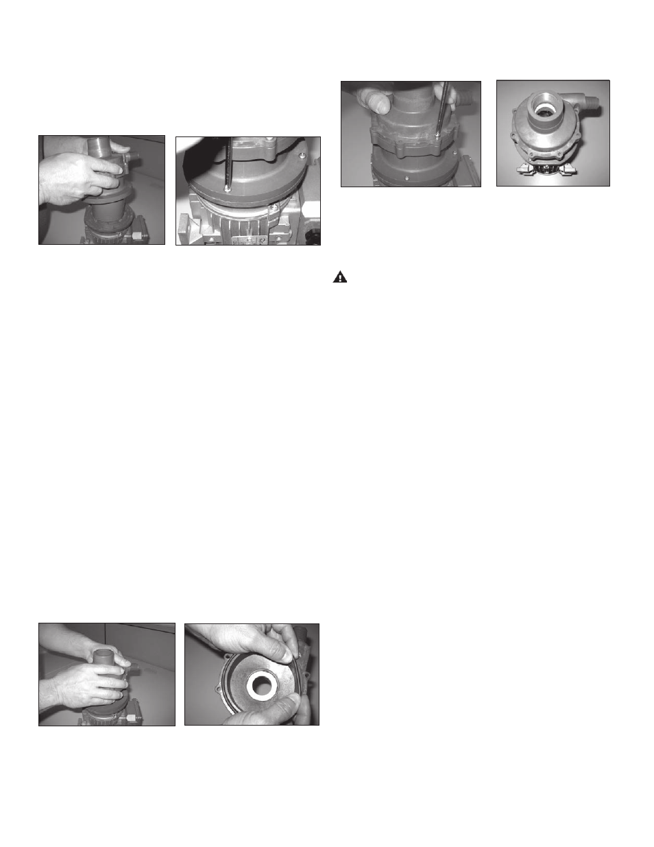
8 . Install the pump end on the motor/drive magnet assembly .
Carefully slide the pump onto the drive magnet assembly .
See figure 7 .
9 . Secure the pump to the motor adapter flange (item 6) with
(4) motor adapter screws (item 8) . Hand tighten screws be-
ing careful not to over tighten . See figure 8 .
Figure 7
Figure 8
10 . Rotate the motor fan or turn the impeller to ensure that there
is no binding in the pump .
11 . Proceed to Installation Section .
Section II – Installation
Mounting
Motor feet should be securely fastened to a solid foundation .
Instructions for horizontal discharge installation:
Note: The pump ships from the factory so the discharge will be
in a vertical orientation . These instructions allow a horizontal
discharge .
1 . Place the pump & motor in an upright position on the fan end
of the motor . Remove (8) housing screws (item 7) . Pull the
housing away from the motor adapter / barrier (item 4) and
remove the o-ring (item 2) . Reinstall the housing in the 3:00
position looking from the pump side . Note: O-ring will be
lubricated from the factory and should not require additional
lubrication . See figure 9 .
2 . Reinstall the o-ring onto the housing (item 1) . If o-ring will
not stay in place it may be necessary to roll the o-ring under
when installing it on the housing . See figure 10 .
Figure 9
Figure 10
3 . Align the holes in the housing with the motor adapter /
barrier . Push the housing with o-ring in place straight down
to seat the o-ring . Hold the housing in place and reinstall the
(8) housing screws (items 7, 7A) in a star like pattern using
Figure 11
Figure 12
Piping
CAUTION: The NPSH available must be greater than the
NPSH required . Filters, strainers and any other fittings in the
suction line will lower the NPSH available and should be
calculated into the application .
• Install the pump as close to the suction source as possible .
• Support the piping independently near the pump to eliminate
any strain on the pump casing . In addition, the piping should
be aligned to avoid placing stress on the pump casing .
• The suction side of the pump should be as straight and short
as possible to minimize pipe friction .
• Keep bends and valves at least ten pipe diameters away
from the suction and discharge .
• The suction line should be at least as large as the suction
inlet port or one pipe size larger so that it does not affect the
NPSHa . Do not reduce the suction line size .
• The suction line should not have any high spots . This can
create air pockets . The suction piping should be level or
slope slightly upward to the pump .
• A check valve and control valve (if used) should be installed
on the discharge line . The control valve is used for regulating
flow . An isolation valves on both the suction and discharge
is used to make the pump accessible for maintenance . The
check valve helps protect the pump against damage from
water hammer . This is particularly important when the static
discharge head is high .
• If flexible hose is preferred, use a reinforced hose rated for
the proper temperature, pressure and is chemically resistant
against the fluid being pumped .
• The suction valve must be completely open to avoid restrict-
ing the suction flow .
• It is advisable to install a flush system in the piping to allow
the pump to be flushed before the pump is removed from
service .
4
the Phillips-head screwdriver . Hand tighten screws being
careful not to over tighten . See figures 11 & 12 .
NOTE: Install two long screws (item 7A) inserting one on
either side of the discharge nozzle . See figure 12 .