Finish Thompson DB3, 4, 5 & 5.5 Series User Manual
Page 6
Section I - Assembly
Pumps with Motors
Proceed to Installation Section
Pumps Without Motors
Tools Required: Metric socket set, 7 mm socket (63 frame), 8 mm
socket (71 frame), 2 .5 mm (56 frame), 3 mm and 4 mm Allen
wrenches, and Phillips-head screwdriver .
1 . Remove the pump, drive magnet assembly and hardware
package from the carton .
CAUTION: Keep away from metallic particles, tools and
electronics . Drive magnets MUST be free of metal chips .
WARNING: Keep the drive magnet away from the open end
of the motor adapter and barrier . Strong magnetic attraction
could allow the drive hub to enter the motor adapter result-
ing in injury or damage .
Figure 1
3 . Install the motor adapter flange (item 6) on the motor face
using motor adapter flange bolts (item 12) .
NOTE: Apply anti-seize compound on the threads of the
bolts . Hand tighten bolts being careful not to over tighten .
See figure 3 .
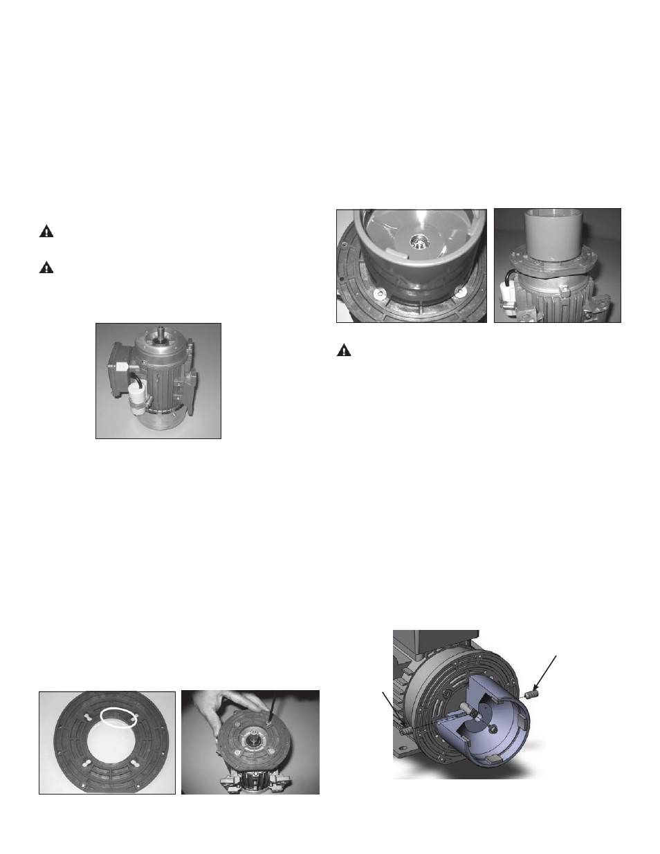
2 . Place motor on the fan end . See figure 1 .
NOTE: The DB3, 4 & 5 pumps mount to either IEC
Figure 2
56, 63, 71 B14 frame motors depending on which
motor adapter is ordered . The motor adapter flange
(item 6) can be used for either frame depending on
which side is used . See stamped identification on
the flange . See figure 2 . DB5 .5 pumps mount to IEC
63 and 71 frame motors .
4 . Make sure the motor shaft is clean and free of burrs . Coat
the motor shaft with anti-seize compound . If not installed
insert key supplied with motor into keyway on motor shaft .
NOTE: The outer drive is precision machined and has a bore
tolerance of +0 .001/-0 inch . It may be necessary to tap the
drive on with a soft mallet .
5 . Slide the outer drive magnet assembly (item 5) onto the mo-
tor shaft until the motor shaft contacts the snap ring in the
bore of the drive . Turn the drive by hand to make sure it
rotates freely . See figures 4 & 5 .
Figure 4
Figure 5
WARNING: Be careful, magnets will try to attract tools .
6 . Secure the drive on the motor shaft using bolt, lock washer
and flat washer (items 9, 10, 11) . Coat the bolt threads with
anti-seize compound . Thread the bolt into the end of the mo-
tor shaft (while holding the outer drive to prevent it from
turning) . See figure 6 .
Tighten the bolt using the 2 .5 mm allen wrench (56 frame),
7mm socket (63 frame) or 8 mm socket (71 frame) to the
following torque rating:
• 56 frame (M3) = 8 in-lbs ( .9 N-m)
• 63 frame (M4) = 15 in-lbs (1 .7 N-m)
• 71 frame (M5) = 30 in-lbs (3 .4 N-m)
Figure 6
3
Figure 3
7 . Tighten two set screws (item 5B) to a torque of 75 in .-lbs .
(8 .5 N-m) using a 1/8” Allen wrench . See figure 6 .