Finish Thompson DB3, 4, 5 & 5.5 Series User Manual
Page 10
3 . To reinstall the original drive or a new drive, follow the in-
structions from Section I – Assembly, Pumps without Motors,
Steps 4 - 6 .
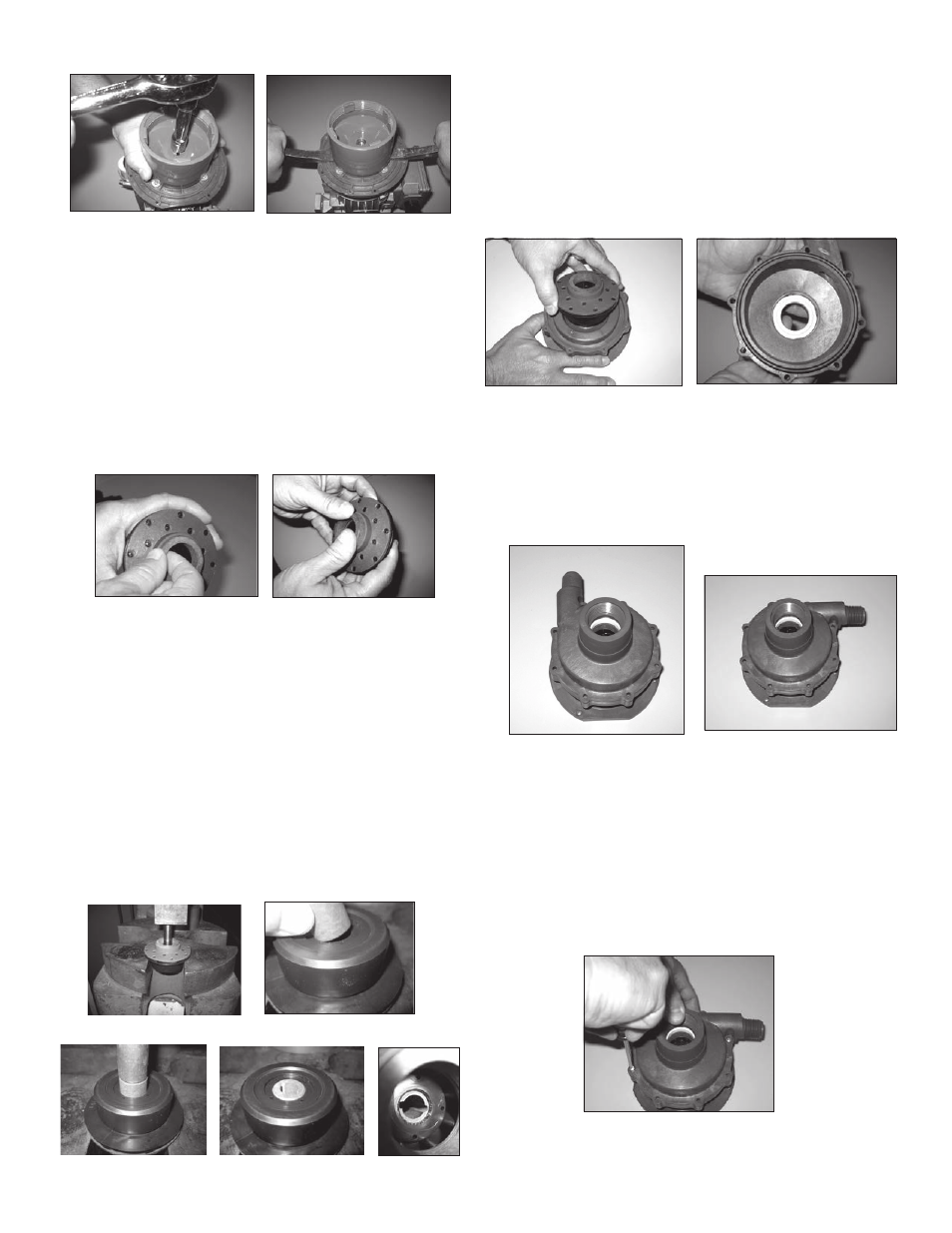
Thrust Ring Replacement
1 . Thrust ring (item 3A) is held in-place with a press fit . Using
fingers, pliers or flat head screwdriver pry ring up and out of
the holder . See figure 24 .
2 . To reinstall simply press the thrust ring into the impeller by
hand . See figure 25 .
Figure 24
Figure 25
Bushing Replacement
To remove the bushing, place the impeller assembly in an arbor
press . Insert a 1/2” (12 .7mm) diameter plastic or wood dowel
through the eye of the impeller and press the bushing out . See
figure 26 .
To replace the bushing (item 3B), place the top of the impeller on
an arbor press with the thrust ring face down . Insert the front of
the bushing into the center of the impeller assembly & press into
place using a ¾” (19 mm) diameter plastic or wood dowel until
the bushing reaches the shoulder molded into the inner drive .
See figures 27, 28, 29 & 30 .
Figure 26
Figure 27
Figure 28
Figure 29
Figure 30
Section VI - Reassembly
1 . Place impeller assembly (item 3) into the motor adapter /
barrier (item 4) . See figure 31 .
2 . Install o-ring (item 2) onto housing (item 1) . Lubricate the o-
ring with P80 or a compatible lubricant . If o-ring will not
stay in place it may be necessary to roll the o-ring under
when installing it on the housing . See figure 32 .
3 . With the discharge port oriented in either a vertical
(12:00) or horizontal (3:00) position, align the holes of the
housing with the motor adapter / barrier . The flat side of the
motor adapter / barrier aligns with the motor feet or bottom
of the pump . See figures 33 & 34 . See note on page 4, step 3
of Mounting .
Figure 31
Figure 32
Figure 33
Vertical Discharge
Figure 34
Horizontal Discharge
4 . Push the housing with o-ring in place straight down to seat
the o-ring . Hold the housing in place & reinstall the (8) hous-
ing screws (item 7) in a star like pattern using the phillips
head screw driver . Hand tighten screws being careful not to
over tighten . See figure 35 .
5 . To complete the reassembly go to Section I – Assembly,
Pumps without Motors, Steps 4 - 10 .
Figure 35
Figure 22
Figure 23
7
NOTE: Install two long screws (item 7A) inserting one on
either side of the discharge nozzle .