Edc wiring work sheet, Middle connector (back view, wire side), P-110 – Electronics International MVP-50P User Manual
Page 61
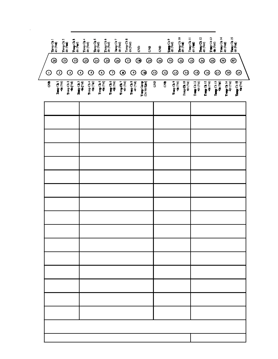
EDC Wiring Work Sheet
Middle Connector (Back View, Wire Side)
EDC-33P-4/6
EDC-33P-4/6
EDC-33P-4/6
EDC-33P-4/6
EDC-33P-4/6
EDC Input
EDC Pin #'s
(Wire Color for Type K Probes)
Function
Probe, Module or
Direct Connection
Temp Ch 1
+In Pin 2 (Yel)
-In Pin 20 (Red)
EGT 1
Type K
Temp Ch 2
+In Pin 3 (Yel)
-In Pin 21 (Red)
EGT 2
Type K
Temp Ch 3
+In Pin 4 (Yel)
-In Pin 22 (Red)
EGT 3
Type K
Temp Ch 4
+In Pin 5 (Yel)
-In Pin 23 (Red)
EGT 4
Type K
Temp Ch 5
+In Pin 6 (Yel)
-In Pin 24 (Red)
EGT 5 (6-cyl)
Type K
Temp Ch 6
+In Pin 7 (Yel)
-In Pin 25 (Red)
EGT 6 (6-cyl)
Type K
Temp C h7
+In Pin 8 (Yel)
-In Pin 26 (Red)
OIL T
Typ K Fltrd
Temp Ch 8
(Best for OAT)
+In Pin 9 (Yel)
-In Pin 27 (Red)
OAT
Typ K Fltrd
Temp Ch 9
+In Pin 13 (Yel)
-In Pin 31 (Red)
Temp Ch 10
+In Pin 14 (Yel)
-In Pin 32 (Red)
CHT 1
Typ K Fltrd
Temp Ch 11
+In Pin 15 (Yel)
-In Pin 33 (Red)
CHT 2
Typ K Fltrd
Temp Ch 12
+In Pin 16 (Yel)
-In Pin 34 (Red)
CHT 3
Typ K Fltrd
Temp Ch 13
+In Pin 17 (Yel)
-In Pin 35 (Red)
CHT 4
Typ K Fltrd
Temp Ch 14
+In Pin 18 (Yel)
-In Pin 36 (Red)
CHT 5 (6-cyl)
Typ K Fltrd
Temp Ch 15
+In Pin 19 (Yel)
-In Pin 37 (Red)
CHT 6 (6-cyl)
Typ K Fltrd
An EDC Temp Channel may be configured to measure a temperature or other functions. See the "List of Allowable
Functions and Probes for the EDC Inputs" for more information.
Note: Any EDC Input not used should be marked "N/A" under Function.
0425051-1
P-110
P-110
P-110
P-110
P-110 (6-cyl)
P-110 (6-cyl)
P-120
P-128
P-100
P-100
P-100
P-100
P-100 (6-cyl)
P-100 (6-cyl)
MVP-50P-4/6
MVP-50P-4/6
MVP-50P-4/6
MVP-50P-4/6
MVP-50P-4/6
Note: Temp Inputs may also be used to measure Digital or Analog signals.