13 install the fuel flow transducer, End view – Electronics International MVP-50P User Manual
Page 32
24
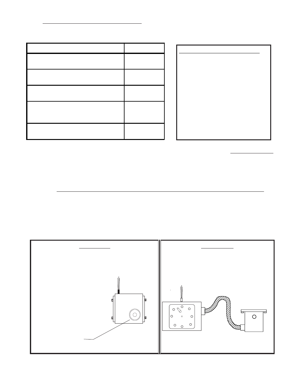
2.13 Install the Fuel Flow Transducer:
Mount the Fuel Flow Transducer using the appropriate drawing found on the following pages.
Fuel Flow
Transducer
1/4" NPT
Note:
•The direction of the flow of
fuel through the transducer
is marked on the trans-
ducer.
• Mount the transducer with
the wires pointing up, or
the cap with five bolts
pointing up or the output
pointing up or any combi-
nation thereof.
End View
End View
End View
End View
End View
Side View
Side View
Side View
Side View
Side View
If the transducer is more than 4" per foot higher
than the carburetor or fuel servo port, put a loop
in the fuel line between the transducer and the
carburetor or fuel servo. This will allow bubbles
to vacate the Flow Transducer.
Fuel Flow Trans-
ducer
Carburetor or
Fuel Servo
OUT
Aircraft Configuration
Drawing #
Fuel injected engine without a fuel return line
from the fuel servo (most Lycomings).
1229932 or
1229931
Fuel injected engine with a fuel return line from
the fuel servo (most Continentals).
0415941
Carbureted engine with a fuel pump and no fuel
return line.
1229932 or
1229931
Carbureted engine with a fuel pump and a fuel
return line (requires an FFDM-1 Module).
1229932 or
1229931, and
1015941
Carbureted engine with a gravity feed fuel
system (requires an FT-90 Flow Transducer).
1229932 or
1229931
Fuel Flow Transducer Selection:
FT-60 (Red Cube): For 0 to 350 HP
Engines.
FT-90 (Gold Cube): For 350 to 550
HP Engines.
FT-180 (Black Cube): For 550+ HP
Engines.
(See the transducer specification for
pressure drops at a given flow rate.)
Note:
Note:
Note:
Note:
Note: If your engine is equipped with a pressure carburetor with a fuel return line from the carburetor
back to the fuel tank, you will need to install two flow transducers: one in the feed line from the fuel
pump to the carburetor and one in the return line from the carburetor back to the fuel tank. Also, a Fuel
Flow Differential Module (FFDM-1) will need to be installed. See drawings 1229932 and 1015941 on
the following pages.
Note:
Note:
Note:
Note:
Note: Insure the fuel flow transducer is appropriate for the horsepower of the engine
Insure the fuel flow transducer is appropriate for the horsepower of the engine
Insure the fuel flow transducer is appropriate for the horsepower of the engine
Insure the fuel flow transducer is appropriate for the horsepower of the engine
Insure the fuel flow transducer is appropriate for the horsepower of the engine.
A.
A.
A.
A.
A. The transducer output port should be mounted lower, even with or no more than 4" per foot higher
than the carburetor inlet port (or fuel servo on a fuel-injected engine). If this is not possible, a loop
should be put in the fuel line between the Fuel Flow Transducer and the carburetor or fuel servo (see
diagram below). This loop is intended to vacate air and keep it from getting trapped in the fuel
transducer.