Edc wiring work sheet, Bottom connector (back view, wire side) – Electronics International MVP-50P User Manual
Page 103
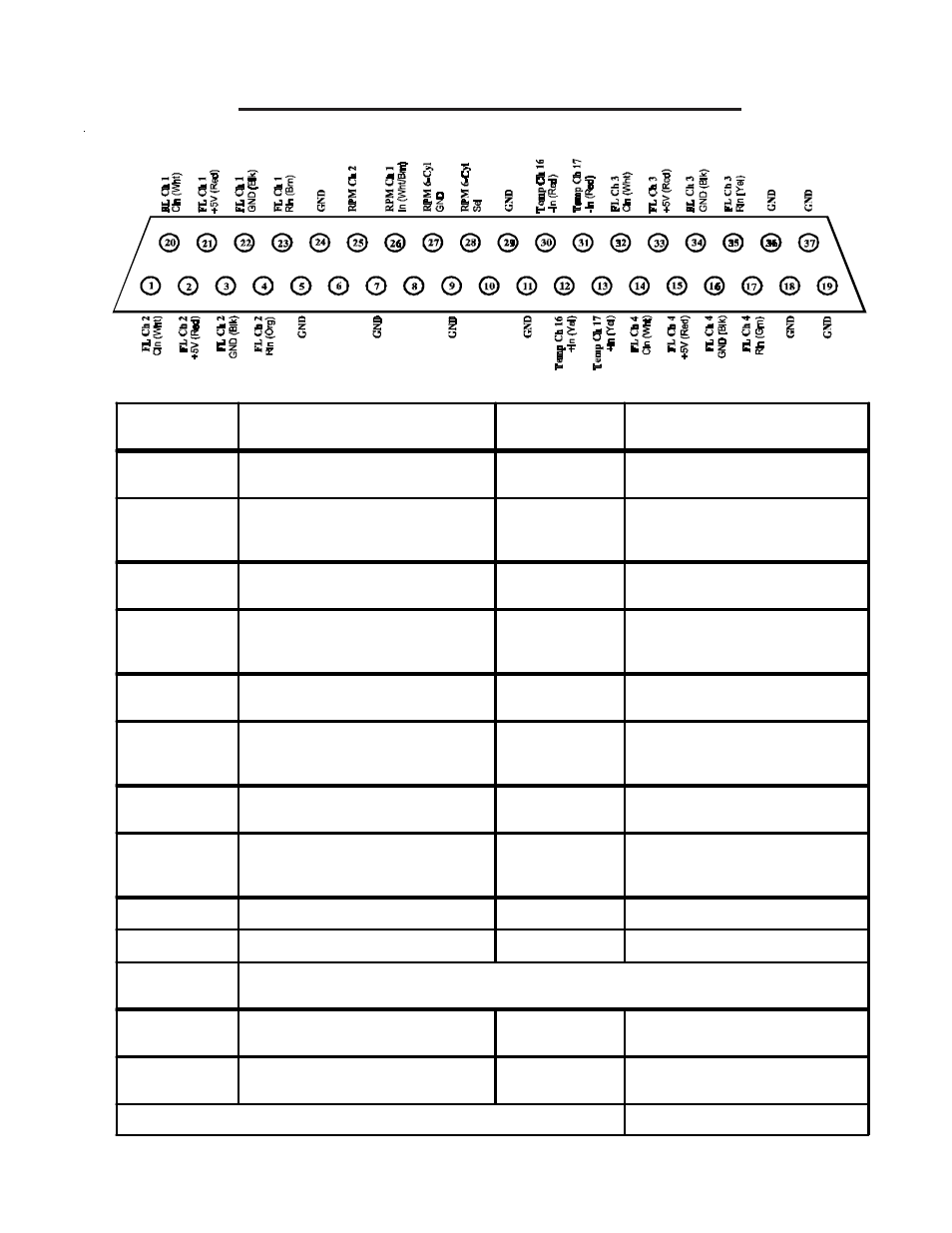
EDC Wiring Work Sheet
Bottom Connector (Back View, Wire Side)
EDC-33P-8
EDC-33P-8
EDC-33P-8
EDC-33P-8
EDC-33P-8
EDC Input
EDC Pin #'s
& Wire Colors
Function
Probe
FL Ch 1
(Resistive Input)
Rin Pin 23 (Brn)
(Requires a RFLM-4 Module)
FL Ch 1
(Capacitive Input)
Cin Pin 20 (Wht)
+5V Pin 21 (Red)
Gnd Pin 22 (Blk)
FL Ch 2
(Resistive Input)
Rin Pin 4 (Org)
(Requires a RFLM-4 Module)
FL Ch 2
(Capacitive Input)
Cin Pin 1 (Wht)
+5V Pin 2 (Red)
Gnd Pin 3 (Blk)
FL Ch 3
(Resistive Input)
Rin Pin 35 (Yel)
(Requires a RFLM-4 Module)
FL Ch 3
(Capacitive Input)
Cin Pin 32 (Wht)
+5V Pin 33 (Red)
Gnd Pin 34 (Blk)
FL Ch 4
(Resistive Input)
Rin Pin 17 (Grn)
(Requires a RFLM-4 Module)
FL Ch 4
(Capacitive Input)
Cin Pin 14 (Wht)
+5V Pin 15 (Red)
Gnd Pin 16 (Blk)
RPM Ch 1
In Pin 26 (Wht/Brn)
LEFT (mag)
Ring Terminal Isolator
RPM Ch 2
In Pin 25 (Wht/Orange)
RIGHT (mag)
Ring Terminal Isolator
RPM Select
Open for 7, 8, & 9 Cyl Engines and 4 Cyl High (>4500) RPM Engines.
Short Pin 28 to 27 for High RPM(>4,500) 6 & 8 Cyl Engines.
Temp Ch 16
+In Pin 12 (Yel)
-In Pin 30 (Red)
Temp Ch 17
+In Pin 13 (Yel)
-In Pin 31 (Red)
0425051-4
+5V
+5V
+5V
In (White/Org)
Page 2 of 2