12 install the shunt – Electronics International MVP-50P User Manual
Page 29
Gear Up Warning: To provide a Gear Warning the MVP must monitor Gear Position, Airspeed
and Manifold pressure. A voice warning (for experimental aircraft only) is activated on the
following logic:
(((((Any Gear is up -OR-
-OR-
-OR-
-OR-
-OR- the Unsafe Indicator is on))))) -AND-
-AND-
-AND-
-AND-
-AND- Airspeed is less than a set value -----
AND-
AND-
AND-
AND-
AND- Manifold Pressure is less than a set value.
Note: See the “Aircraft Number, Gear Warning and TAS Setup” screen to set values.
21
EDC
Temp or Resistive Fuel
Level Channel.
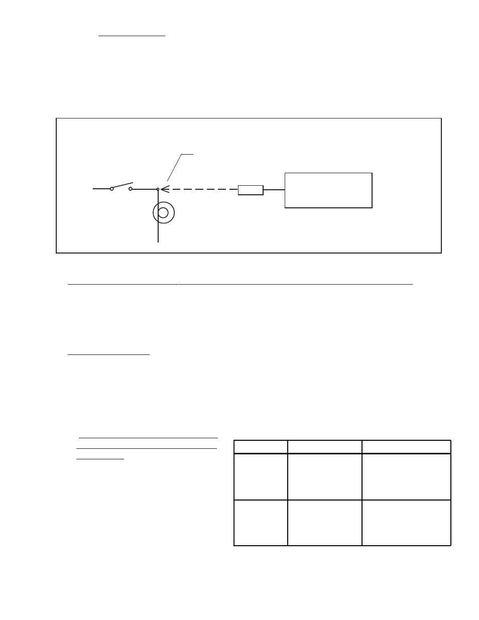
VI-221
Tap into the switched side of the Light
Gear or Unsafe Light
Gear and Unsafe Interface Circuit
2.11 Install the CO Detector, G-Sensor and/or Other Available MVP Options:
The CO Guardian Remote Mounted CO Detector, G-Sensor and other MVP options listed on EI’s price sheet are
provided with there own installation instructions. These items should be installed and wired in accordance with the
accompanying instructions. Note: The CO Detector connects to Port 3 Input on the MVP.
2.12 Install the Shunt:
An external shunt is a strip of metal, usually mounted on a bakelite base. This metal is made of special alloys to
produce a very small, precise signal when current passes through it. It is not affected by temperature changes.
If your aircraft currently has an external shunt you can calibrate your MVP to that shunt. The MVP can be
calibrated to match any shunt on the market.
A.
A.
A.
A.
A. Determine How the Shunt will be
Determine How the Shunt will be
Determine How the Shunt will be
Determine How the Shunt will be
Determine How the Shunt will be
Installed in the Aircraft’s Electri-
Installed in the Aircraft’s Electri-
Installed in the Aircraft’s Electri-
Installed in the Aircraft’s Electri-
Installed in the Aircraft’s Electri-
cal System:
cal System:
cal System:
cal System:
cal System:
There are two common methods of
installing a shunt in an aircraft. One
method is with the shunt in the alterna-
tor lead. The other method is with the
shunt located in the battery lead. The S-
50 shunt that comes with the MVP-50
package may be installed using either
method. The advantages and disadvan-
tages of each method are listed below.
There are few disadvantages with either method. Although EI’s test pilot has a slight preference for
Installation Method
Advantages
Disadvantages
Battery Lead:
1. Shows load current on the
ground (engine off) and during
an alternator failure.
2. All Warning Lights are
operational.
1. Cannot show load current during
flight or when the engine is running.
Alternator Lead:
1. Shows load current during
flight or when the engine is
running.
2. All Warning Lights are
operational.
1. Cannot show load current when
the engine is off or during an
alternator failure.
S0224921