Mode 1 logic flow chart, Mode 1 logic flow chart appendix a-5 – Electro Cam 5000 Series User Manual
Page 56
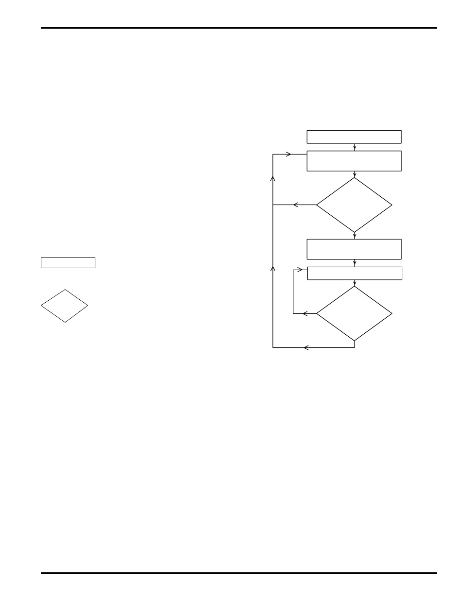
Mode 1 Logic Flow Chart
Appendix A-5
Mode 1 Logic Flow Chart
The flow chart to the right details how Mode 1 operates.
The control’s response to any set of conditions can be
determined by stepping through the flow chart blocks using
those conditions when decision blocks are encountered.
The flow chart shows when the group enable input is armed
and disarmed. Mode 1 logic never disables the outputs,
however, Motion ANDing (FCN 7) can disable outputs that
are operating in Mode 1.
How to Use the Flow Chart
To use the block diagram assume that the control is
continuously processing the blocks at a very fast rate and
is never stopped on any one block. The control will get
stuck processing the same path of blocks repeatedly (loop)
until a condition changes within one of the decision blocks
in that loop which alters the path. Response to a condition
change is almost instantaneous so the new conditions
established in the next loop take affect quickly. Note that
the logic path can only flow in the direction of the arrows,
never against them.
Rectangle Block
Output enable/disable status or a
logic memory flag is altered.
Diamond Block
A yes/no decision is made based on
the condition stated within the block.
Mode 1 Flow Chart Blocks
1. Control powers up and assumes position determined by
last offset programmed from keyboard (FCN 2).
2. Group enable input is armed. Enable the outputs to cycle
at their programmed on/off setpoints.
3. Check for leading edge of group enable input signal. If it
occurred go to step 4, if not loop back to step 2.
4. Reset group position to zero. Disarm group enable input.
5. Enable the outputs to cycle at their programmed on/off
setpoints. Go to step 6.
6. Check if group position has reached next input window
(CHN 9X). If yes go to step 2, if no loop back to step 5.
Note: Position can reach input window from forward or
reverse direction.
Power Up
Input Armed
Outputs Enabled
Input Signal
Leading Edge
Occurred?
no
Position Resets to zero
Input Disarmed
yes
Outputs Enabled
no
yes
Next Input
Window Reached?
1
2
3
4
5
6
TASK
DECISION