Module wiring: outputs, Module wiring - outputs, Analog output – Electro Cam 5000 Series User Manual
Page 16
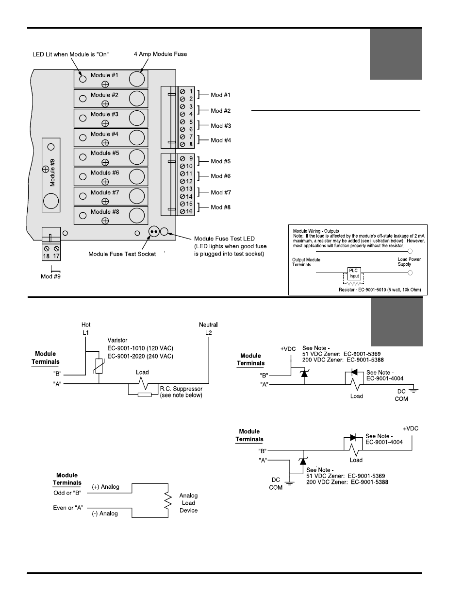
3-4 Wiring
Slimline I/O Modules on Controller Back: Specifications
PS-5021
PS-5121
PS-5024
PS-5124
Notes:
• A module is required for each Input or Output used. See
Appendix for module specs.
• AC and DC modules can be mixed as needed.
• Input modules can be used only with 5024 and 5124 units.
• Output modules act like switches; they do not supply power
to loads.
• Analog modules may be installed in Position 9 only, and
only on units ordered with option “-A”.
• Module Fuses: 4 Amp, #PS-9005-0004 (Wickman 19370-K)
• Odd Terminals:
(+) or hot
Even Terminals: (-) or load
Back View of Controller Body
Module Wiring - Outputs
PS-5X01
PS-5X04
PS-5X21
PS-5X24
AC Output
DC Output
• Most applications will not need the varistor or R-C suppressor shown
above. However, when other switching devices are in series or parallel
with the AC module, voltage spikes may damage the module. Use one
of the following two methods to suppress voltage spikes.
• For infrequent switching, connect a varistor (MOV) across the terminals.
• For continuous switching, wire an R-C suppressor in parallel with the
load.
• Control must have Option “-A” to use analog output module.
• Analog output modules source the analog signal.
• Analog output signals are isolated.
• Caution: Do not apply external voltage to an analog module or you will
damage it.
Analog Output
Sourcing
Sinking
• Most applications will not need the diodes shown above. However,
highly inductive DC loads may damage modules by generating voltage
spikes when switched off. Suppress these loads using one of these two
methods:
• Connect a Zener diode across the terminals. This will not significantly
increase the load turn off time. Voltage rating of the diode must be
greater than the normal circuit voltage.
• Connect a reverse-biased diode across the load. This may increase the
load turn off time.
Odd or
Even or
Odd or
Even or
Odd or
Even or