Resolver wiring and dimensions, 14 wiring, Resolver dimensions – Electro Cam 5000 Series User Manual
Page 26: Standard resolver cables
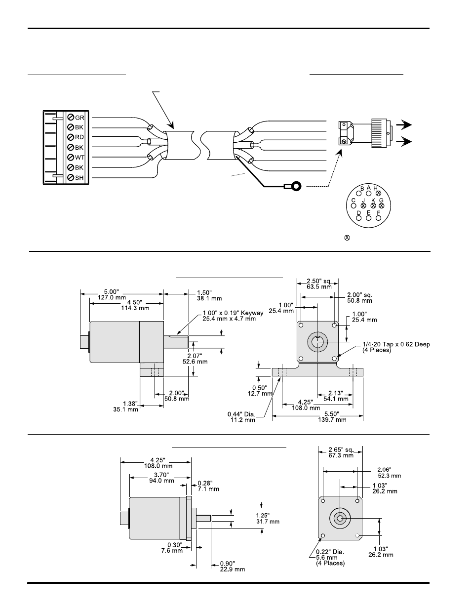
3-14 Wiring
RESOLVER DIMENSIONS
Resolver Wiring and Dimensions
Shield
Red
Green
Black
Black
White
Black
Pin A - Black
Pin D - Red
Pin E - Black
Pin F - White
Pin B - Green
Pin C - Black
Cable Type:
3 individually shielded pairs, 22 gauge
Shield
(see note below)
Front View
(pin out)
= Not Used
Shielding Note: Resolver cables made after 3-2-93 have a ring lug on a black shield wire at
the resolver end. The ring lug should be attached to one of the resolver connector strain relief
screws to protect against static discharge through the resolver cable. In some installations, it
may be advisable to disconnect the ring lug to prevent ground loops through the cable shield.
Consult Electro Cam if electrical noise problems are suspected.
Shield
Connector - Resolver End
PT# PS-5300-01-MSC
(ITT Cannon # KPT-06-F-12-10-S)
Connector - Controller End
PT# PS-5300-01-TER
(Weidmuller # BLA7 12822.6)
STANDARD RESOLVER CABLES
PT# PS-5300-01-XXX (XXX = LENGTH IN FEET)
S2
S4
S1
S3
R1
R2
Flange Mount Resolver - 3/8" Shaft
Foot Mount Resolver - 3/4" Shaft
0.375/
0.374"
9.53/
9.50 mm
0.749/
0.747"
19.02/
18.97 mm
With Rear Connector (shown):
PS-5238-11-ADR
With Side Connector:
PS-5238-11-ADS
Cable:
PS-5300-01-XXX where “XXX” is length in feet.
With Rear Connector (shown):
PS-5275-11-ADR
With Side Connector:
PS-5275-11-ADS
Cable:
PS-5300-01-XXX where “XXX” is length in feet.