PASCO OS-8170A Brewster’s Angle Accessory User Manual
Page 9
®
Model No. OS-8170A
Brewster’s Angle Accessory
9
®
Controlling the Laser Intensity
1. Place the second optics bench at right angles to the first optics bench at the spot where the
Beam Splitter is mounted.
2. Mount the second High Sensitivity Light Sensor on an Aperture Bracket, and attach the
Aperture Bracket to a Lens Holder. Set the disk on the Aperture Bracket to slit #5.
3. Mount the Light Sensor/Aperture Bracket at the far end of the second optics bench (see Figure
1). Connect a patch cord between an electrical ground and a piece of bare metal on the
Aperture Bracket.
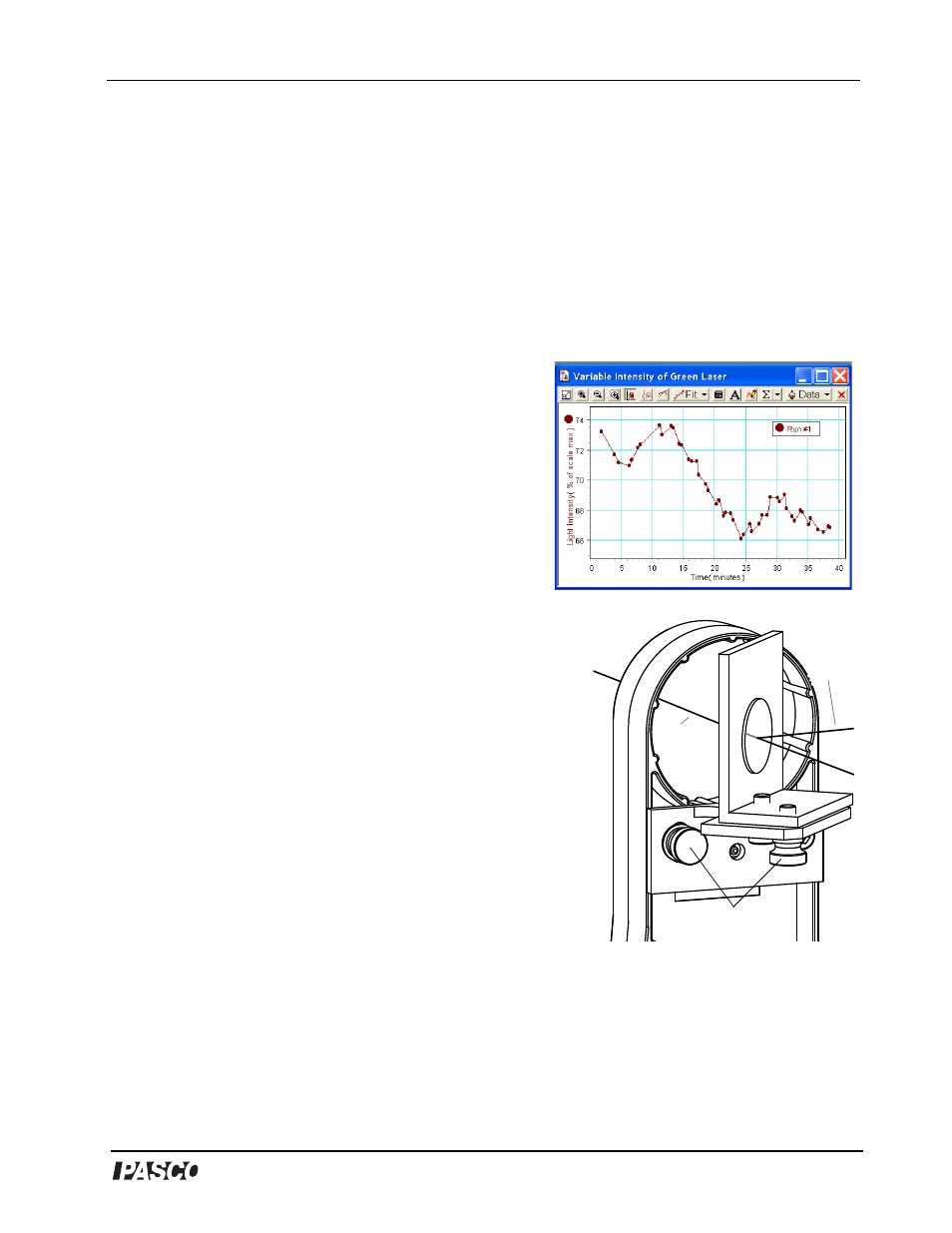
NOTE.: The second High Sensitivity Light Sensor is
used to compensate for the variability of the incident
laser beam intensity (see Figure 7). The second light
sensor on the optics bench measures the relative
incident light intensity (from the Beam Splitter)
while the light sensor on the Spectrophotometer Arm
simultaneously measures the reflected light intensity
(from the “D” Lens through the Analyzing Polarizer).
Any fluctuations in intensity can be normalized by
dividing the reflected light intensity by the relative
incident light intensity.
4. Adjust the position of the second optics bench as
needed until the reflected laser beam from the Beam
Splitter travels to slit #5 on the Aperture Bracket disk in
front of the second Light Sensor.
5. If you need to re-adjust the Beam Splitter, make sure that
the laser beam is still aligned with the first High
Sensitivity Light Sensor.
6. Snap the round Polarizers into both sides of the Lens
Holder, and mount the Lens Holder on the bench
between the Collimating Slits and the Beam Splitter. The
Polarizers help control laser intensity.
7. Rotate the second polarizer (farthest from the laser) to 45
degrees (the indicator is the bottom lip on the lens holder)
and lock it in place by tightening the brass screw. The first
polarizer (closest to the laser) is used throughout the experiment to adjust the light level.
Since the ratio of reflected light to incident light is being measured, better data will be
obtained if the incident light level is kept above 50%.
Figure 7: Variability of Green Laser
Adjustment Screws
Transmitted
Beam
Reflected
Incident
Beam
Figure 8: Adjust the Beam
Splitter as needed