Introduction, Equipment set-up, Assemble the apparatus – PASCO ME-9892 Ballistic Pendulum Accessory User Manual
Page 4
®
B a l l i s t i c P e n d u l u m A c c e s s o r y
I n t r o d u c t i o n
4
Introduction
Use the Ballistic Pendulum Accessory in combination with a Short Range Launcher
and Rotary Motion Sensor (RMS) to measure the velocity of a steel ball and study
rotational collisions. The launcher shoots the ball into the Ballistic Pendulum Acces-
sory. The RMS measures the resulting angular displacement and velocity of the pen-
dulum. The pendulum can be configured to catch the ball or allow the ball to bounce
off. With the addition of the Mini Rotational Accessory, the apparatus can be config-
ured as a physical pendulum or rotational system with adjustable moment of inertia.
This manual includes set-up instructions and experiment instructions.
Equipment Set-up
Assemble the Apparatus
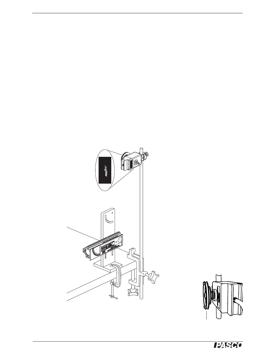
1. Set up the launcher, C-clamp, table clamp, mounting rod, and RMS as shown in
Figure 1. The exact position of the RMS is not important yet. Note that the side
of the RMS without the model number on the label is facing you. (If the RMS is
mounted the other way, it will measure negative displacement.)
Figure 1: Launcher and RMS mounted on rod
2. Slide the three-step pulley onto the RMS shaft with the largest pulley out as
shown in Figure 2.
R
O
TA
R
Y MO
TION SENSOR FOR
INTERF
A
CES
ä
Three-step
pulley
Figure 2: Three-step
pulley on RMS