PASCO ME-8089 Computer-Based Centripetal Force Accessory User Manual
Page 5
®
Model No. ME-8089
Centripetal Force Accessory
5
Note: If using a PASPORT interface, connect the photogate to a PASPORT Photogate Port.
4. Slide the pivot block through the groove to the center of the platform. (Note: The indent
mark on the pivot block must face the zero position on the measuring tape.) Tighten in
place.
5. Slide the fixed mass holder onto the platform. Slide the nuts into the T-slot and tighten the
thumbscrews over the nuts.
6. Insert the sliding mass holder through the groove on the top of the platform, such that the
side indent faces the measuring tape.
7. Mount a 90 cm stainless steel rod vertically into a second “A” base stand.
8. Attach a Multi-Clamp to the upper end of the stainless steel rod (See Figure 3a).
9. Insert the shorter stainless steel rod (45 cm) horizontally into the Multi-Clamp.
Note: With an additional rod and clamp, you can insert another rod into the base stand and a
longer crossbar(rod) into the clamp. This creates a more stable structure.
10. Slide a Force Sensor onto the stainless steel rod and adjust the top screw to anchor it to the
rod (Figure 3a). (Note: Be sure to keep the cords from the sensor out of the path of the
rotating arm.)
11. Attach the ball bearing swivel to the bottom of the Force Sensor.
12. Thread the cable from the swivel hook through the pulley and over the screw of the
“sliding mass” holder (Figure 3b).
13. Move the Force sensor directly over the pivot block in the center of the platform. (Note:
You can adjust the radius of the sliding mass holder by moving the crossbar higher or
lower.)
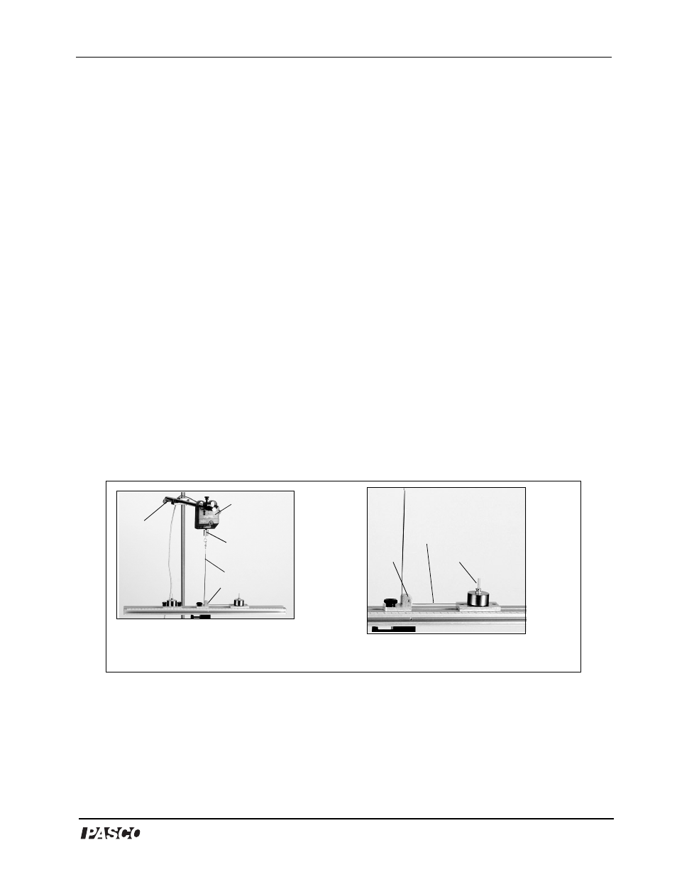
Figure 3a: Mounting the Force Sensor
Figure 3b: Threading the cable through
the sliding mass holder
sliding mass
pulley
cable
swivel
holder
clamp
Force
Sensor
cable
pivot block