About the equipment, Wa-9897 ripple tank, Setup – PASCO WA-9899 Ripple Tank System User Manual
Page 5
®
M o d e l N o . W A - 9 8 9 9
A b o u t t h e E q u i p m e n t
5
About the Equipment
WA-9897 Ripple Tank
The Ripple Tank is designed to be used with the PASCO model WA-9896 Ripple Genera-
tor and Light Source. The tank is 42.5 cm by 42.5 cm by 2.5 cm with four foam “beaches”
and a 0.3 cm thick glass plate. The viewing area is 33 cm by 33 cm. The tank has an
easy-to-use drain pipe consisting of a piece of flexible vinyl plastic tubing and a tube
clamp. The tank is supported by three detachable legs with adjustable feet and comes with
a reflector and projection screen.
The ripple tank also comes with the following: ruler,
pipette, surfactant bottle, storage box, barriers (5 pieces),
refractors (3 pieces), a beaker, and a rod for supporting the
light source.
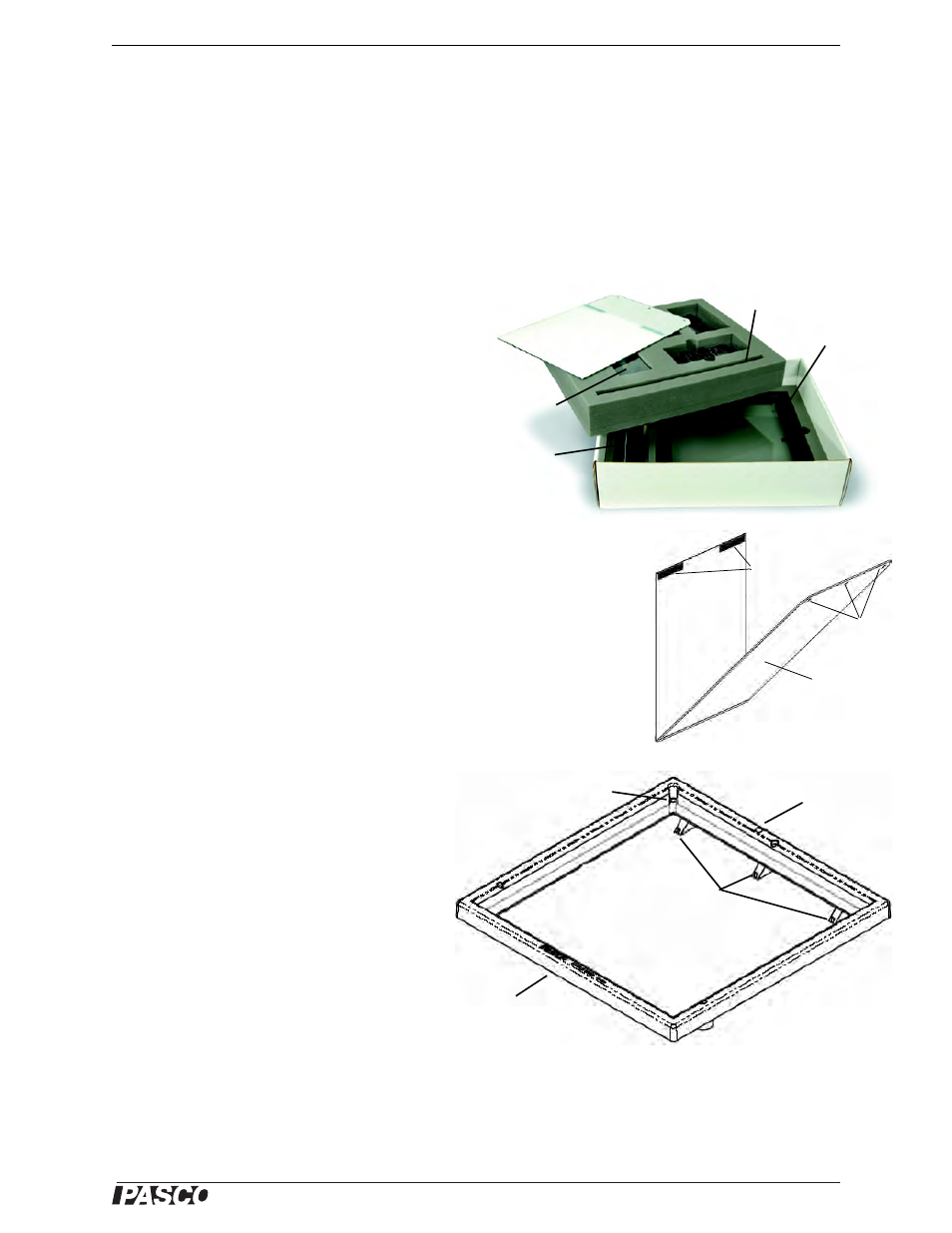
The box in which the Ripple Tank is stored has two layers.
The screen assembly, plastic storage box, rod, and beaker
are in the top layer; the ruler, legs, and Ripple Tank assem-
bly are in the bottom layer. The top layer has areas for stor-
ing the WA-9896 Ripple Generator and Light Source,
including the power adapter and cord.
Screen Assembly
The screen assembly is a
reflector and a projection screen joined at one edge by a strip of flexible tape. Note:
Remove any protective coating from the reflector and the screen before using. The
reflector is aluminized acrylic. The projection screen is translucent plastic.
There are three holes along the top edge of the reflector and two strips of Velcro®
‘loop’ material along the top edge of the projection screen.
Ripple Tank Assembly
The ripple tank assembly has an impact resistant
plastic frame. Below the front edge of the frame is a strip of Velcro® ‘hook’ material
that will hold the ‘loop’ material on the top edge of the projector screen. Below the
back edge of the frame are three pegs that fit into the holes in the top edge of the
reflector. The threaded hole on the top side of the back edge is for the rod that can
support the Light Source that is included in the
WA-9896 Ripple Generator and Light Source. When
the ripple tank is in use, the four foam ‘beaches’
dampen the waves that would otherwise reflect and
disturb the primary wave and interference patterns.
The foam beaches are replaceable. (A variety of
replacement parts are available in the WA-9898 Rip-
ple Tank Replacement Set.)
The ripple tank’s drain pipe is a piece of flexible
vinyl tubing attached below the drain hole at the back
corner of the tank. Squeeze the sides ot the tube
clamp on the drain pipe to tighten the clamp on the
tubing. Pull downward on the lip of the tube clamp to
loosen the clamp.
Setup
To setup the ripple tank, screw the legs into the threaded holes on the underside near the
two front corners of the tank, and under the midpoint of the back edge. Place the ripple
Screen
assembly
Ripple Tank
assembly
Rod
Plastic
storage
box
Legs and
ruler
Holes
Velcro®
‘loop’
material
Reflector
Drain hole
Pegs
Strip of Velcro® ‘hook’
material (not shown)
Projection
screen
Threaded hole