PASCO WA-9899 Ripple Tank System User Manual
Page 26
®
R i p p l e T a n k S y s t e m
E x p e r i m e n t 5 : I m a g e F o r m e d b y a P l a n e M i r r o r
26
8.
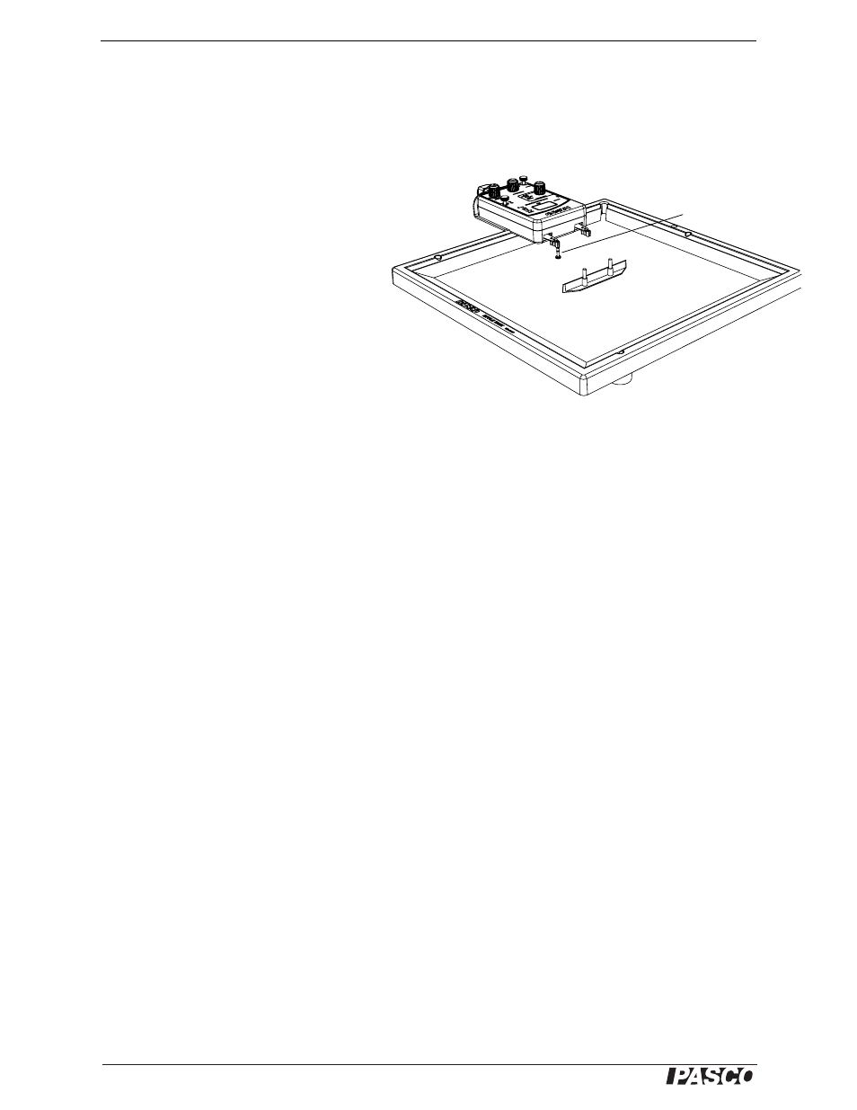
Arrange the long barrier near the middle of the tank so that the midpoint of the
barrier is aligned with the ripple arm that holds the standard dipper. Adjust the
barrier so it is parallel to the front of the ripple generator as in Figure 5.2.
Procedure
1.
Turn on the ripple generator and the
light source. Set the light source to
‘STROBE’. Set the frequency to 20 Hz
and the amplitude to slightly less than
half of maximum. Adjust the amplitude
to make a clear wave pattern.
2.
On the paper below the tank, trace the
outline of the standard dipper and the
long barrier.
3.
Sketch the wave fronts and the rays that
represent the waves as they move from
the dipper and reflect from the long bar-
rier.
4.
Measure and record the distance from the outline of the standard dipper to the
outline of the long barrier.
5.
Place the ruler on the paper with one end of the ruler at any point on the line that
indicates the side of the long barrier that faces the standard dipper. Orient the
ruler so that it crosses the reflected circular wave fronts at a right angle. Draw a
line along the ruler to indicate the ray for the reflected wave fronts.
6.
Move the end of the ruler to a new point on the outline of the long barrier. Orient
it again so it crosses the reflected circular wave fronts at a right angle. Draw a
new line along the ruler to indicate the ray for the reflected wave fronts from this
point.
7.
Turn off the ripple generator.
8.
Extend the two ruler lines until they cross. The point where they cross is the cen-
ter of the reflected circular wave fronts. This center represents the position of the
image.
9.
Measure and record the perpendicular distance from the front side of the barrier
to the position of the image.
Questions
1.
Where is the position of the image located relative to the long barrier and the
standard dipper?
2.
How does the distance to the position of the image compare to the distance from
the standard dipper to the long barrier?
Figure 5.2: Position of Barrier
standard dipper