Din connector specifications, Approximate response of sensor – PASCO CI-6630 BROAD SPECTRUM LIGHT SENSOR User Manual
Page 3
012-08541B
Broad Spectrum Light Sensor
3
®
10
1
100
GAIN
TARE
1
4
3
5
2
6
7
8
Collecting Data with the Broad Spectrum Light
Sensor
DIN Connector Specifications:
1: analog output (+), -10 to +10 V
2: analog output (-), signal ground
3: (no connection)
4: + 5 V DC power
5: power ground
6: +12 VDC power
7: -12 VDC power
8: (no connection)
Zeroing the Broad Spectrum Light Sen-
sor
1. Attach the shutter to the sensor and mount the sensor to
an experimental apparatus.
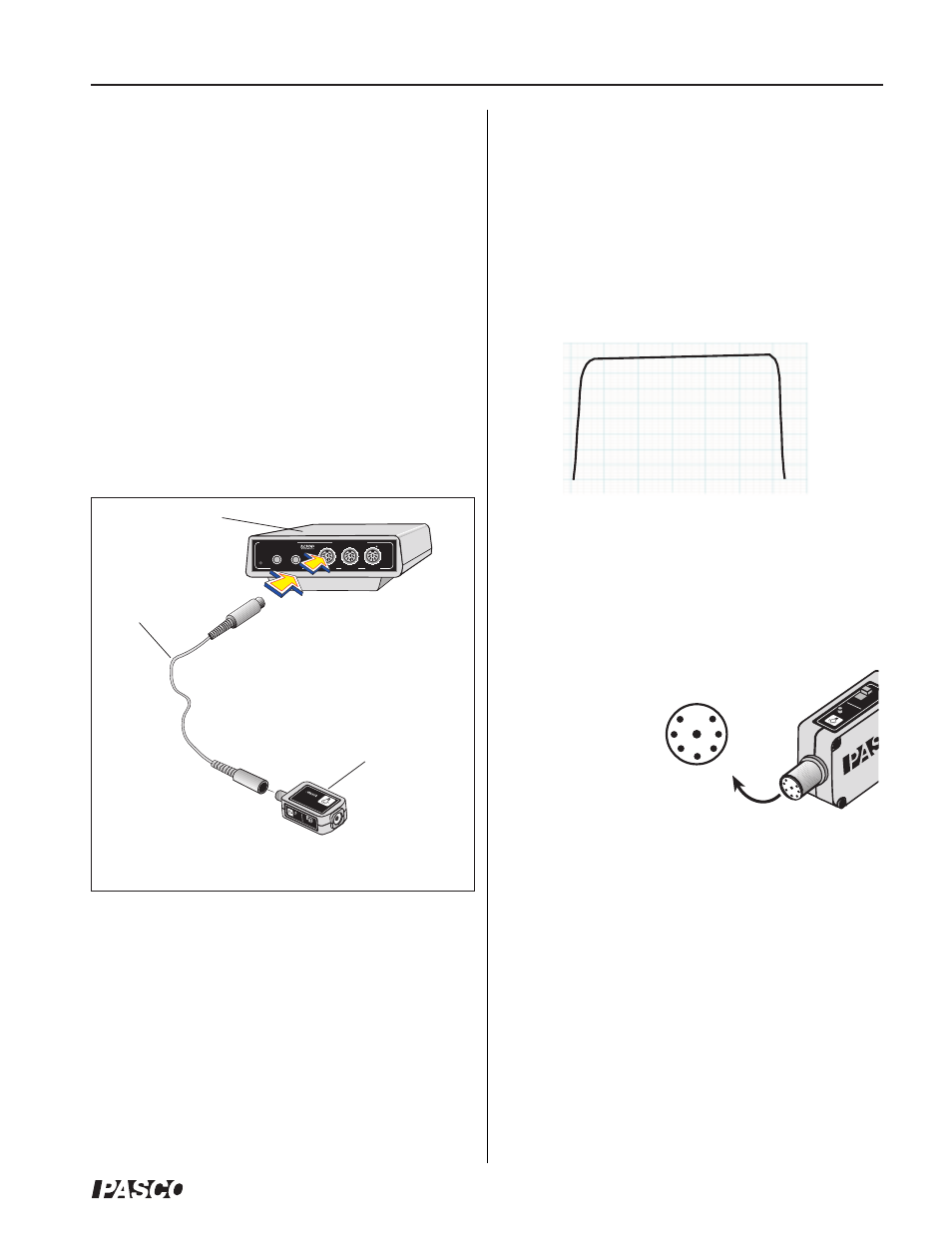
2. With the 8-pin cable, connect the Broad Spectrum
Light Sensor to any analog channel (A, B, or C) on the
ScienceWorkshop interface (Figure 4). (Note: The
sensor also plugs directly into any analog channel.)
5. In DataStudio, click the Start button to begin
collecting data.
The TARE button on the top of the sensor is for
zeroing the sensor. Zeroing is particularly useful at
high gain settings where small voltage offsets may
interfere with measurements.
Note: This instruction sheet was written assuming that
the user has a basic familiarity with DataStudio
software. Users can gain basic skills by working
through the tutorial in the DataStudio sofware.
Figure 4: Plugging the sensor and cable into a
ScienceWorkshop interface
10
1
100
GAIN
TARE
Interface
500
1
2
GAIN=1,10:ISOLATED
GAIN =
1,10: REF TO GND
GAIN =
1: REF TO GND
A
s
C
ON
ANALOG CHANNELS
B
n
DIGITAL CHANNELS
ScienceWorkshop
BRO
AD SPECTR
UM
LIGHT SENSOR
CI-6630
300nm -10,000nm
P
R E S S
T
O
L O
G
®
interface
sensor
cable
3. In DataStudio, set up your experiment in the
Experiment Setup window.
4. Select a gain setting on the sensor box. If you expect
the light intensity levels in your experiment to be dim,
move the gain switch to either 10x or 100x. If you
expect the light intensity levels to be bright, adjust the
gain setting to the 1x position.
wavelength (nm)
Approximate Response of Sensor
percent transmittance
(%)
100
1000
10,000
10
20
30
40
60
70
80
90
100
50