Equipment included, Scienceworkshop – PASCO CI-6630 BROAD SPECTRUM LIGHT SENSOR User Manual
Page 2
Broad Spectrum Light Sensor
012-08541B
2
®
10
1
100
GAIN
TARE
BR
OAD SPECTR
UM
LIGHT SENSOR
CI-6630
300nm -10,000nm
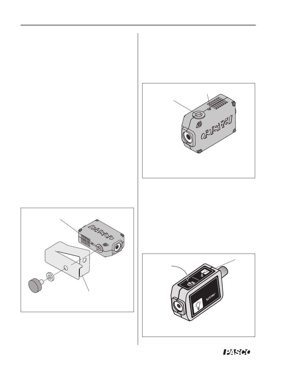
alignment hole
1/4-20
threaded
connector
Equipment included:
•
Broad Spectrum Light Sensor (CI-6630)
•
1/4-20 X .375” thumbscrew (617-008) with
0.250 I.D. washer (615-011)
•
Shutter bracket (648-06954)
•
8-pin connector cable (514-06329)
Additional equipment required:
•
ScienceWorkshop
®
computer interface
•
DataStudio
®
software (version 1.8.5 or higher)
Adjust the gain for
the light conditions.
Tare
button
Figure 2: Connector and alignment hole for mounting
Figure 3: Setting the gain on the Infrared Sensor
Using the Shutter Bracket with the Sensor
The spring-loaded shutter bracket keeps extraneous
radiated energy from heating the sensing element
either before or during measurements. The tab on the
front edge of the shutter bracket is for ensuring
constant spacing between the sensing element and a
hot object, such as when performing comparative
radiant energy measurements.
Attach the shutter bracket to the Infrared Sensor unit,
with the included thumbscrew and washer, as shown
in Figure 1. Do not over tighten the thumbscrew.
Mounting the Sensor to Experimental
Apparatus
Use the 1/4-20 threaded connector on the bottom of
the sensor box to secure the Broad Spectrum Light
Sensor to an experimental apparatus (Figure 2). The
alignment hole is for holding an alignment pin, which
is included on some PASCO products.
Adjusting the Gain on the Sensor
The sensor has three gain settings: 1X, 10X and 100X.
The gain settings on the sensor, coupled with the user-
selectable gain on the
ScienceWorkshop
interface,
allow for a very broad range of measurements with the
Broad Spectrum Light Sensor. (Note: Adjusting the
sensor’s gain only changes the signal voltage, not the
actual light intensity measurement. You can change the
gain to a maximum of +/- 10 volts.)
Figure 1: Attaching the shutter bracket
shutter bracket
1/4-20 threaded
connector