Equipment setup, Mounting on included base, Mounting on an optics bench – PASCO TD-8580A Thermal Cavity User Manual
Page 2: Thermistor sensor connection, Power supply connection
®
Thermal Cavity
Equipment Setup
2
With an Infrared Sensor students can examine IR light emission from each of the
cube's surfaces. The addition of a Light Sensor, Rotary Motion Sensor, Aperture
Bracket, and Linear Translator allows students to scan the cavity and generate inten-
sity versus position graphs for visible and infrared light.
The apparatus can be mounted on the included rectangular base or on a PASCO Basic
Optics Bench.
Equipment Setup
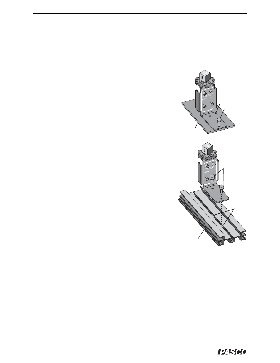
Mounting on Included Base
1. Place the apparatus upright with the chassis (horizontal support piece)
on the base.
2. Align the outer hole in the chassis with the tapped hole in the base.
3. Insert a thumbscrew through the hole in the chassis and thread it into
the base.
Mounting on an Optics Bench
Mount the apparatus on a Basic Optic Bench for use with a Linear Trans-
lator, Aperture Bracket, and other optics equipment.
1. Slide both nuts into the center slot of the optics bench.
2. Align the holes on the chassis of the Thermal Cavity apparatus with
the nuts.
3. Insert the thumbscrews through the holes in the chassis and thread
them loosely into the nuts.
4. Move the apparatus to the desired position on the optics bench.
5. Tighten the thumbscrews.
Thermistor Sensor Connection
Use the included cable to connect the white pair of jacks labeled
“THERMISTOR SENSOR” to a ScienceWorkshop Thermistor Sensor, a PASPORT
Temperature Sensor, or the temperature port of the Xplorer GLX interface.
You can also use a stand-alone resistance meter or multimeter to read the temperature.
Measure the resistance between the white jacks and use the conversion formula on
page 7 to calculate the temperature.
Power Supply Connection
The Thermal Cavity requires a power supply capable of 10 V and 1 A.
1. Use two banana patch cords to connect the power supply to the red pair of jacks
labeled “INPUT POWER.”
2. Set the voltage as high as 10 V. The cube will reach 100 °C in about 30 minutes.
TD-8
580A
THER
MAL C
AVITY
INPUT
POWER
(10 VOL
T MAX)
Thumbscrew
Chassis
Base
TD-8580A
THERMAL
CAV
ITY
INPUT
POW
ER
(10 V
OLT
MAX)
Thumbscrews
Nuts
Optics Bench
IMPORTANT: Do not
apply voltage to the white
thermistor jacks.