Further investigation – PASCO ET-8782 Energy Transfer– Thermoelectric User Manual
Page 21
Model No. ET-8782
Experiment 2: Load Resistance and Efficiency
21
®
2) For output loads less than and greater than the optimal value, why does the peltier generate
less power?
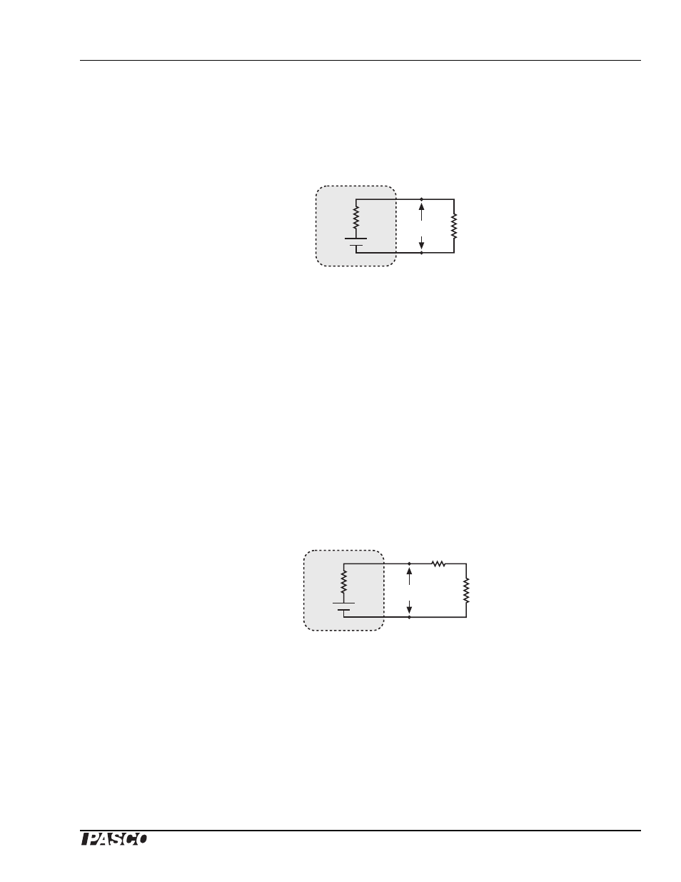
All real electrical power supplies (including the peltier heat engine) have an internal resistance,
R
i
. They can be modeled as an ideal voltage source in series with a resistor, as shown below (with
an output load connected).
The voltage of the ideal voltage source, V
NL
, is called the no-load voltage. For a peltier heat
engine V
NL
depends only on
∆T.
3) Under what condition does the output voltage (V
out
) equal V
NL
?
4) How would you directly measure V
NL
at
∆T = 30
°
C?
5) Write a theoretical equation for output power, P, in terms of V
NL
, R
i
and R
L
. Make a graph of
P vs. R
L
(choose some arbitrary values for V
NL
and R
i
). Based on your equation and graphs,
under what condition is P at its maximum?
6) In this experiment, one of the data points was taken with R
L
= 0. According to your equation,
what is the theoretical power generated when R
L
= 0? Was this the case in your experiment?
There is another source of resistance that we haven’t considered yet, which is the resistance of the
traces, leads and sensors in the circuit. Let’s call it R
T
. If we add in R
T
, the circuit can be modeled
thus:
7) Rewrite the theoretical equation for P taking R
T
into account.
8) Fit this equation to your experimental data. What is the no-load voltage at
∆T = 30
°
C? What
is the internal resistance of the peltier? What is R
T
?
Further Investigation
1.
Make a direct measurement of the no-load voltage at
∆T = 30
°
C.
2.
Make a direct measurement of R
T
(or measure as much of it as possible).
Peltier
Heat Engine
V
NL
R
i
R
L
V
out
+
+
Peltier
Heat Engine
V
NL
R
i
R
L
V
out
+
+
R
T