PASCO SE-8658A PERMANENT MAGNET MOTOR User Manual
Page 18
14
Permanent Magnet Motor 012-07210A
Setup
1. Gently lower the armature onto the shaft with the dual slip-ring commutator pointed down.
Carefully rotate the armature back and forth to separate the brushes and allow the commutator to
slip down between them. If necessary, insert a pencil or similar object down between the brushes.
Use only the most delicate force to avoid bending the brushes and necessitating adjustments or
repairs.
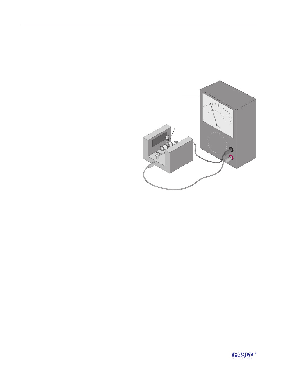
2. Connect the motor to the meter by one of these
methods (Figure 2.1):
•
Insert banana plugs into the openings in the
ends of the plastic brush holder;
•
Grip the brass posts of the brush holder with
large alligator clips; or
•
Attach small alligator clips to the ends of the
brass strips that serve as brushes.
Procedure
Part A: AC Generator
1. During the first part of this experiment, the dual
slip-ring commutator should be pointed down,
between the brushes. If it is not, remove the
armature from the shaft by grasping it between
the thumb and forefinger and rotating it back and
forth while lifting gently. Sometimes it may be
necessary to insert a pencil between the brushes
to gently separate them so that they don’t prevent
removal of the armature.
2. The cylindrical ceramic magnet may be used to determine the polarity of other magnets. The
painted face of the magnet is its North Pole (north-seeking pole). [You can verify this by hanging
the magnet from a thread and observing that the painted face points toward magnetic North (the
earth’s north magnetic pole, located in northern Canada).] Determine the polarity of the field
magnets by holding the ceramic magnet near its rectangular poles. In the event that both poles of
the ceramic magnet attract a pole piece, the stronger attraction occurs when opposite poles are
together. Label the pole pieces N and S using small strips of tape.
3. Examine the armature closely, and imagine current entering one of the two slip rings from a brush.
Trace the path of the current through the wire to the coil, through the coil, through the wire to the
coil on the opposite side of the armature, through that coil, and through the wire to the other split ring
and into the second brush. By carefully examining the part of the coils where the leads emerge from
the coil, it should be possible to determine the direction in which the wire is wound on the coil. Can
you verify that the current maintains its same direction of rotation as it leaves one coil and enters the
other? This means that the two coils of the armature act as a single coil. Ask for help if you
cannot.
voltmeter or
galvanometer
Figure 2.1
Experimental Setup
split ring
commutator