Experiment 2: rotational inertia of disk and ring – PASCO PS-2120A Rotary Motion Sensor User Manual
Page 9
®
P S - 2 1 2 0 A
E x p e r i m e n t 2 : R o t a t i o n a l I n e r t i a o f D i s k a n d R i n g
9
E x p e r i m e n t G u i d e
Experiment 2: Rotational Inertia of Disk and Ring
*Click the equipment item to go to the PASCO web site.
Purpose
The purpose of this experiment is to experimentally find the rotational inertia of a ring and a disk and verify that
these values correspond to the calculated theoretical values.
Theory
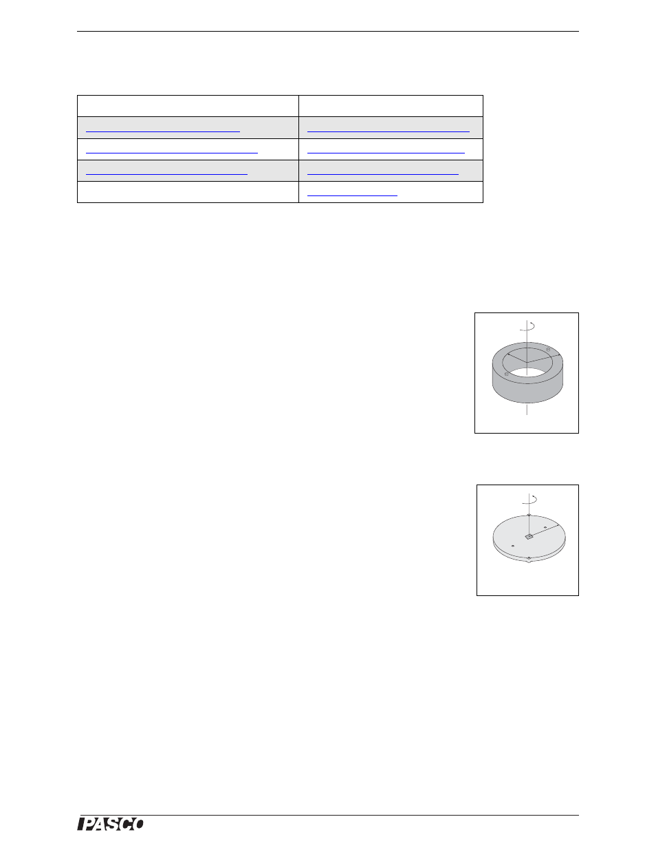
Theoretically, the rotational inertia, I, of a ring about its center of mass is given by:
where M is the mass of the ring, R
1
is the inner radius of the ring, and R
2
is the outer
radius of the ring. See Figure 2.1.
The rotational inertia of a disk about its center of mass is given by:
where M is the mass of the disk and R is the radius of the disk. See Figure 2.2. To find
the rotational inertia experimentally, a known torque is applied to the object and the
resulting angular acceleration is measured, Since
= I
,
where
is the angular acceleration, which is equal to a/r (a = acceleration), and is the
torque caused by the weight hanging from the thread that is wrapped about the 3-step
Pulley on the Rotary Motion Sensor. The torque is given by:
where r is the radius of the pulley step about which the thread is wound, and T is the tension in the thread when
the apparatus is rotating.
Applying Newton’s Second Law for the hanging mass, m, gives:
See Figure 2.3. Solving for the tension in the thread gives:
Once the angular acceleration is measured, the radius and the linear acceleration, a, can be obtained for the calcu-
lation of the torque.
Equipment Required*
Equipment Required*
Interface
Paper clips (for masses <1 g)
Figure 2.1: Ring
I
1
2
---M R
1
2
R
2
2
+
=
I
1
2
---MR
2
=
Figure 2.2: Disk about
center of mass
I
---
=
rT
=
F
mg
T
–
ma
=
=
T
m g
a
–
=