Armature plate assembly replacement, Pivot stud adjustment – Dings Dynamics Group 60 Series Coupler NEMA 2 User Manual
Page 6
Armature Plate Assembly Replacement
Caution: Load to be removed or blocked. Brake will be inop-
erative during this procedure.
Refer to Figs. 3, 6 and 10.
If you replace the magnet assembly, it may be necessary to
replace the armature (25J). If it is badly deformed, it will be dif-
ficult to make the magnet quiet.
1.
To replace, remove operator assembly (25) from brake. See
“Friction Disc Replacement Steps 1-4.”
Remove nuts (25U), springs (25G), and carriage bolts (25F).
This will allow the armature plate to be removed from mag-
net bracket.
2.
Remove screws (25S), lockwasher (25R), locking plate
(25Q), two screws (25L), spacers (25N), and armature (25J).
Inspect these parts and shock mount (25P). If worn, replace
them also.
3.
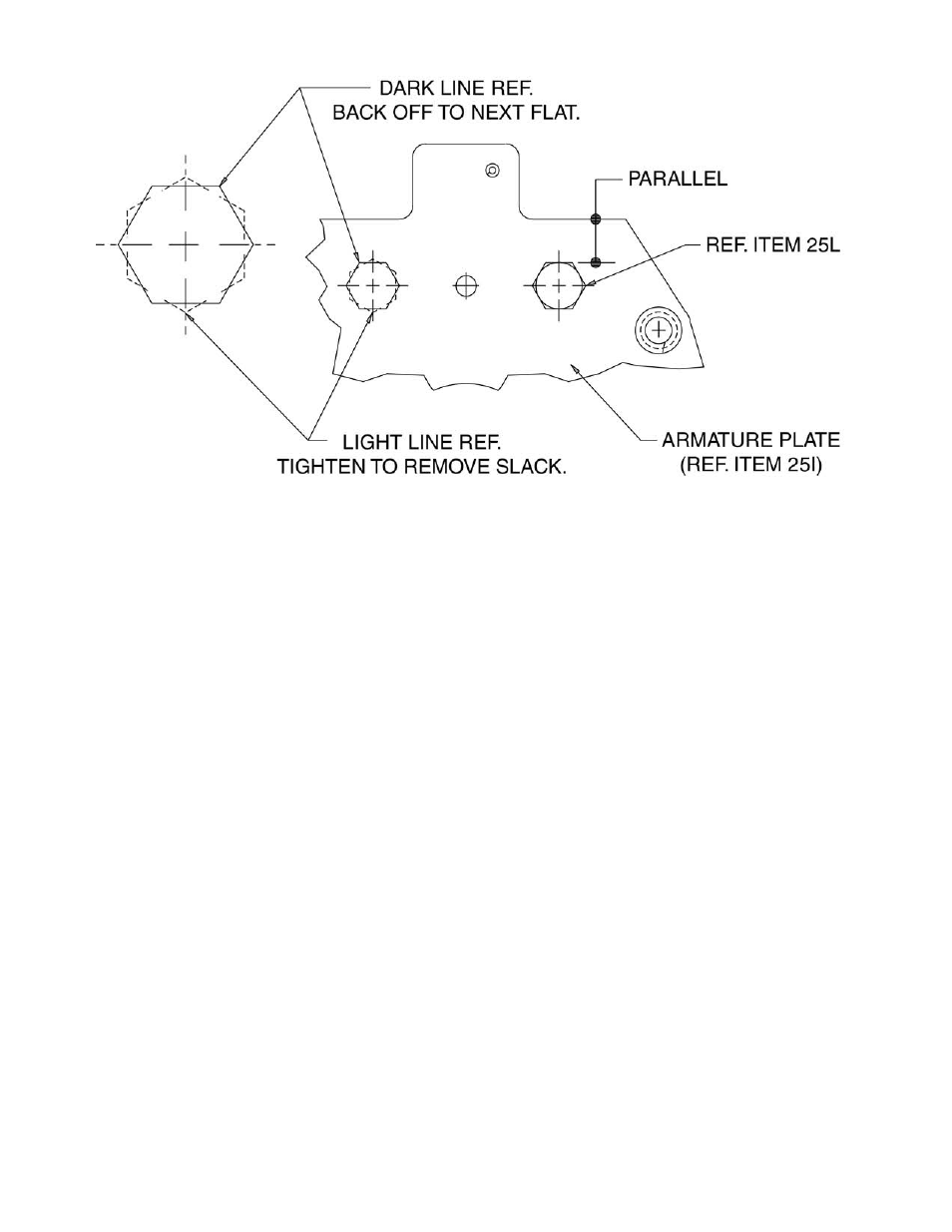
Put armature in place (ground side up) and install spacers
(25N) and screws (25L).
NOTE: Screws (25L) should be tightened to remove slack
only. Then back off, counterclockwise on screw so that the
next flat on screw is parallel with edge of the armature plate
(25I). See Fig. 6.
4.
Reassemble to magnet bracket (25B) using items (25U),
(25G), and (25F). Reassemble operator assembly to brake
bracket. Set magnet air gap “A” and set torque springs
(25G) to 1” as shown in Fig. 3.
Pivot Stud Adjustment
Caution: Load to be removed or blocked. Brake will be inop-
erative during this procedure.
Refer to Fig. 6.
This adjustment is made at the factory and may be required
when replacing the magnet assembly (25A) or the armature
(25J).
The purpose is to adjust the height of the armature plate (25I)
so that the armature (25J) is parallel to the magnet (25A) when
the brake is energized. This is required so that the magnet will
be quiet.
NOTE: Adapter housing (7) must be removed to make this
adjustment.
1.
To adjust: Hold the nut (6) which is adjacent to washer (4)
and loosen the other nut (6) and remove it from the stud.
2.
Energize the magnet and slowly tighten remaining nut (6)
counterclockwise slowly until the magnet becomes noisy.
Turn magnet on and off several times until you find the
position where the magnet first becomes quiet.
At this point turn nut (6) 1/3 turn (two flats) in a clockwise
position. Hold nut in this position and turn magnet on and
off to make sure the magnet does not become noisy.
3.
Holding this nut in place, screw on other nut and tighten it
against the nut you are holding. Tighten firmly.
4.
Operate the manual release. If the release does not operate
properly, see “Manual Release Adjustment” on next page.
Figure 6
6