Piping/mounting, Electrical, Disassembly – MP Pumps FRX-125 INSTALL User Manual
Page 2: Inspect pump parts, Reassembly
PIPING/MOUNTING:
The pump has 1 1/4” N.P.T. inlet and 1” N.P.T. outlet pipe
connections. Use pipe sealant on the threads and other
connections. The base does not require direct mounting if
one of the pipe flanges is rigid mounted. Do not rigid mount
both the flanges and the base to avoid mounting toler-
ances that may distort the motor base. Install the pump
with the shaft in a horizontal direction. Never install the
pump vertical with the motor below the pump.
ELECTRICAL:
The motor must be protected from over current by using a
fuse or circuit breaker (see chart below for correct protec-
tion). The proper minimum wire size is stated for each
voltage application. Make sure that the pump has the
proper voltage rating to match the installation power. Do not
use or install if the voltage on the label is different than the
installation. All wire connections must be secure and sealed
to protect against arcing.
Follow all local installation codes.
MOTOR VOLTAGE FUSE/CB WIRE SIZE
ON NAME PLATE AMPS AWG
12VDC 15 14
24VDC 10 16
32VDC 6 18
110VAC 2 18
OPERATION:
The pump should be operated with liquid in the pump,
otherwise seal damage may occur. If an inlet valve is
present, the valve should always be completely open
during operation to avoid cavitation. An oulet valve may
be used to throttle the flow rate. Avoid repeated starts
and stops; the pump can operate for a long period of
time without any flow.
REPAIR AND MAINTENANCE:
The pump has a carbon/ceramic seal that may last several
thousand hours based upon the application. If the motor is
replaced, the mechanical shaft seal should also be replaced.
A seal that leaks will show leakage through the slot be-
tween the pump housing and the motor. Extreme leakage
may damage the motor bearings and contaminate the in-
side of the motor.
DISASSEMBLY:
1. Remove the four cover screws and remove the
cover discarding the o-ring.
2. Secure the motor shaft at the back of the motor and
remove the impeller by rotating it counter clockwise.
3. Remove the spring keeper, spring and rotating portion
of the seal by pulling them off by hand.
A screwdriver may be used to pry the seal up if it is sticking.
4. Remove the four capscrews that hold the
housing / adaptor assembly onto the motor. Remove
the housing / adaptor assembly and push the seal
seat out from the back side using a screwdriver.
INSPECT PUMP PARTS:
Always replace the mechanical seal. Check the seal for dry run
wear or damage. Check the motor shaft for wear at the secondary
sealing surface from the mechanical seal. If worn, replace the
motor. Check the motor bearings by rotating the motor by hand. If
the shaft rotation is not smooth or has radial/axial endplay,
replace the motor. Check the impeller running surface between
the impeller and cover. If the surfaces are worn or irregular, replace
each item.
Clean the parts that are to be reused using a solvent or mild
cleaner. Remove abrasive material.
REASSEMBLY:
1. Press the new seal seat into the pump housing.
A light lubricant may be used to aid the assembly.
Install the pump housing / adaptor assembly onto the
motor and fasten with the four capscrews.
2. Install the rotating portion of the mechanical seal
by sliding the seal (carbon side down) over the motor shaft.
Place the spring and spring keeper over the back of the
rotating portion of the seal.
3. Place the impeller onto the shaft, taking care to
pilot the spring keeper onto the shoulder at the back
of the impeller. Thread the impeller onto the motor
shaft until it bottoms out on the shaft. Thread locking
grade Loctite should be used to secure the nut.
4. Stretch the o-ring over the cover pilot. Install the cover
onto the housing and fasten the capscrews and
lockwashers.
FORM 3809A (05-07)
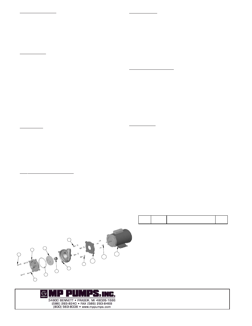
ITEM
NO.
PART NO.
DESCRIPTION
QTY.
1
21250
CAPSCREW - S.S. - 5/16-18 X 1.13
4
2
21238
LOCKWASHER - S.S. - 5/16
4
3
35141
COVER - S.S.
1
*
4
34555
O-RING - VITON
1
5
35343
IMPELLER - S.S. - 4.45 DIA.
1
*
6
35052
SEAL - 5/8 T-21
1
7
35139
HOUSING - S.S.
1
8
21251
CAPSCREW - S.S. - 3/8-16 X 7/8
4
9
21266
LOCKWASHER - S.S. - 3/8
4
10
34928
ADAPTOR PLATE -C
1
11
21504
CAPSCREW - Z.P.S. - 1/4-20 X 5/8
4
12
35159
ELEC. MTR. - 3/4 H.P. 1 PH. 56J TEFC
1
1
2
3
4
5
6
7
8
9
10
11
12