MP Pumps FRX-75 SP INSTALL User Manual
Page 2
®
FORM 3807A (08-06)
PIPING/MOUNTING:
The pump inlet and outlet has 3/4" pipe connections. Use
pipe sealant on the threads and other connections. The
base does not require direct mounting if one of the pipe
flanges is rigid mounted. Do not rigid mount both the flanges
and the base to avoid mounting tolerances that may distort
the motor base. Install the pump with the shaft in a
horizontal direction. Never install the pump vertical with the
motor below the pump.
ELECTRICAL
:
The motor must be protected from over current by using a
fuse or circuit breaker (see chart below for correct protection).
The proper minimum wire size is stated for each
voltage application. Make sure that the pump has the
proper voltage rating to match the installation power. Do not
use or install if the voltage on the label is different than the
installation. All wire connections must be secure and sealed
to protect against arcing.
Follow all local installation codes.
MOTOR VOLTAGE
FUSE/CB
WIRE SIZE
ON NAME PLATE
AMPS
AWG
12VDC 15 14
24VDC 10 16
32VDC 6 18
115VAC 2 18
230VAC
1
18
OPERATION:
The FRX 75 SP is a self-priming centrifugal pump
and only requires priming prior to its initial start-up.
This is accomplished by removing the priming plug and
filling the chamber with liquid.
The pump will retain sufficient liquid for self-priming
thereafter.
REPAIR AND MAINTENANCE:
DC motor brush life expectancy is 6,000 hours total brush
life. The motor is not rebuildable after the brushes have
worn to the limits.
The pump has a carbon/ceramic seal that may last several
thousand hours based upon the application. If the motor is
replaced, the mechanical shaft seal should also be replaced.
A seal that leaks will show leakage through the slot between
the pump housing and the motor. Extreme leakage may
damage the motor bearings and contaminate the
inside of the motor.
DISASSEMBLY:
1.
Remove five cover screws and remove the
cover and gasket.
2. Remove snap ring and wear plate.
3.
Secure the impeller and remove the impeller
lock nut. Pull the impeller straight out off the
motor shaft.
4.
Remove the seal-rotating portion by pulling
the seal off by hand.
5. Remove the capscrews that hold the pump housing
onto the motor. Remove the pump housing and push the
seal seat out using a screwdriver.
INSPECT PUMP PARTS:
Always replace the mechanical seal. Check the seal for
dry run wear or damage. Check the motor shaft for wear
at the secondary sealing surface from the mechanical
seal. If worn, replace the motor. Check the motor bearings
by rotating the motor by hand. If the shaft rotation is
not smooth or has radial/axial endplay, replace the
motor. Check the impeller running surface between the
impeller and cover. If the surfaces are worn or irregular,
replace each item.
Clean the parts that are to be reused using a solvent or
mild cleaner. Remove abrasive material.
REASSEMBLY:
1.
Press the new seal seat into the pump housing.
A light lubricant may be used to aid the assembly.
Install the pump housing onto the motor and fasten
the screws through the motor.
2.
Install the rotating portion of the mechanical seal
by
sliding the seal over the motor shaft.
Do not use any lubricant.
3. Place the impeller onto the shaft over the "D" drive
against the shoulder and tighten the impeller lock nut
until the impeller is securely shouldered on the motor
shaft. Thread locking grade Loctite should be used
to secure the nut.
4. Replace wear plate and snap ring. Check the pump
for internal interference by rotating the impeller.
The pump should rotate freely with only seal friction.
5. Install the gasket and cover onto housing
and fasten with capscrews and lockwashers.
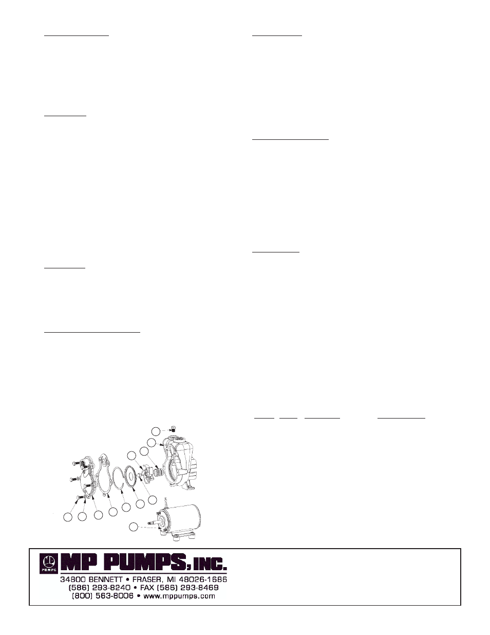
ITEM QTY.
PART NO.
DESCRIPTION
1
5
35039
CAPSCREW - 316 S.S. - 1/4-20 X 5/8
2
5
33564
LOCKWASHER - 316 SS - 1/4
3
1
35024
COVER - 316 SS MACH.
4
1
35025
GASKET - VITON 70 DUROMETER
5
1
35027
RETAINING RING - 316 SS
6
1
35026
WEAR PLATE - 316 SS
7
1
28766
ACORN NUT - 316 SS
8
1
34033
IMPELLER - 316 SS
9
1
34038
MECHANICAL SEAL - VITON
10
1
25022
HOUSING - 316 SS MACH.
11
1
21255
PIPE PLUG - 18" NPT 316 SS
12
1
34036
EL. MOTOR - 12VDC
34293
EL. MOTOR - 24VDC
34504
EL. MOTOR - 115VAC ODP
35178
EL.MOTOR - 115VAC TENV
35179
EL. MOTOR - 230VAC TENV
1
2
3
4
5
6
7
8
9
10
11
12