Installation – Max Machinery 243 Helical Flow Meter User Manual
Page 10
Max Machinery, Inc.
© Copyright 2013
Rev. 002Q4
10
Installation
For optimum performance, install the flow meter on the discharge side of the pump, in one
of the configurations shown on page 11.
The following items and conditions should be considered:
Location: Install the flow meter in a clean, dry area if possible. Avoid areas with high vibration levels.
Line and Bypass Valves: These valves allow filter cleaning or flow meter removal without completely shutting the system
down and draining the lines. They are important for system start up under conditions which could damage the meter,
such as: air in the lines, solid materials (at room temperature), high temperature materials, or initial line surges.
Filtration: Any dirt present in the system can jam or damage the meter. A 150 micron filter is generally recommended,
although materials with very high viscosities may require a coarser filter. For bidirectional flow applications, use a filter
on each side of the flow meter. Materials with fibrous or non abrasive particulate matter may have to be run without
filters. Follow the recommendation of your Max Sales Engineer or consult Technical Service.
Clean Plumbing: Before installing the flow meter, clean the inside of the pipe line with compressed air or steam
(especially when using new pipe). Don’t use water, steam, or compressed air on the meter itself! Remove any protective
covering from the flanges (if applicable).
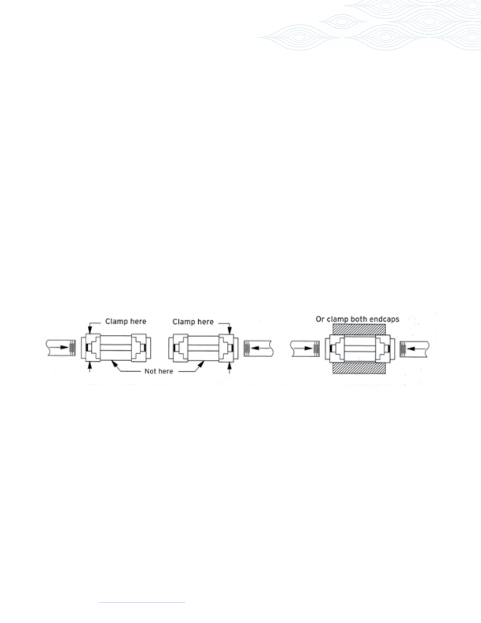
Pipe Threading: When installing pipe to the flow meter, support the nearest end cap or both end caps (as in a vise). Don’t
clamp the flow meter body. This avoids possible misalignment of flow meter components when the pipe is screwed tight.
Check for proper flow meter operation by rotating the timing gear through the transmitter mounting hole. It should
move freely and without noise.
High Temperatures: Use the “Vertical Installation” drawing. This minimizes heat transfer by convection from the
flow meter to the transmitter. The transmitter is the most heat sensitive element in the system and the transmitter
manual should be consulted for specific limits. Optional heating fluid ports are available for the flow meter to keep it at
operating temperature during standby conditions. For substances that are solid at room temperature, these ports are
generally required to keep the material molten and flowing through the meter.
ANSI Flanges: Using the 241, 242 or 243 meters at pressures greater than 500 psi will also require flanges. See the
specifications and bolt torque table on page 12. Max has bolt kits available for flange installations.