Mallory Ignition Mallory HYFIRE V ELECTRONIC IGNITION CONTROL 585 User Manual
Page 4
MALLORY IGNITION
550 MALLORY WAY, CARSON CITY, NV 89701
4
TACHOMETER COMPATIBILITY LIST
Aftermarket
White Wire
Magnetic Trigger
Tachometer
Trigger
Connector
Autogage
29074
29078
Autometer
Ford Motorsport
Moroso
Stewart
29074
29078
S.W. & Bi Torx
Sun
29074
29078
VDO
8910
29078
AMC (Jeep)
29074
29078
Chrysler
29074
29078
Ford (Before 1976)
29074
29078
Ford (After 1976)
29074
29078
GM
Bypass in-lin
Bypass in-line
filter
filter
Imports
29074
29078
Engine Run-On
If your engine continues to run even when the ignition is turned off,
you are experiencing engine run-on. Usually, older vehicles with an
external voltage regulator are susceptible to this condition. Because
the HYFIRE
®
V Ignition Control receives power directly from the bat-
tery, it does not require much current to keep the unit energized. If you
are experiencing run-on, it is due to a small amount of voltage going
through the charging lamp indicator and feeding the small red wire
(even if the key is turned off).
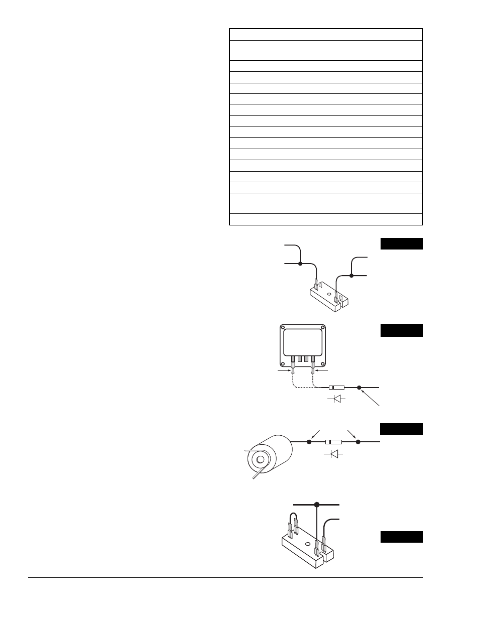
Early Ford and GM: To solve the run-on problem, a diode is supplied
with the HYFIRE
®
V Ignition Control. By installing this diode in-line of
the wire that goes to the charging indicator, the voltage is blocked
from entering the HYFIRE
®
V Ignition Control. Figure 4 shows the
proper diode installation for early Ford and GM vehicles.
NOTE: Diodes are used to allow voltage to flow only one way.
Make sure the diode is installed facing the proper direction, as
shown in Figure 4.
Ford: Install the diode inline to the wire going to the #1 terminal.
GM: Install the diode inline to the wire going to the #4 terminal.
GM 1973-83 with Delcotron Alternators
GM Delcotron alternators use an internal voltage regulator. Install the
diode inline on the smallest wire exiting the alternator (see Figure 5A).
It is usually a brown wire.
Most other applications: To eliminate run-on, connect a Chrysler dual
ballas resistor as shown in Figure 5B.
Misses and Intermittent Problems
Experience has shown that if your engine is misfiring or hesitating at
higher RPM, it is usually not a HYFIRE
®
problem. Most common causes
include a coil or plug wire failure, arcing from the cap or boot plug to
ground or spark ionization inside the cap. Perform the following checks:
Inspect the plug wires at the cap and at the spark plug for a tight
connection. Visually inspect for cuts, abrasions, or burns.
Inspect the primary coil wire connections. Because the HYFIRE
®
V
Ignition Control receives a direct 12 volt source from the battery,
there will not be any voltage at the coil positive (+) terminal, even
with the key turned on. During cranking, or while the engine is run-
ning, very high voltage will be present and no test equipment should
be connected.
WARNING: Do not touch the coil terminals during cranking or
while the engine is running.
Make sure that the battery is fully charged and the connections are
clean and tight, especially if you are not running an alternator. If the
battery voltage drops below 10 volts during a race, the HYFIRE
®
V
Ignition Control output voltage will drop.
Is the engine running lean? Inspect the spark plugs and the entire
fuel system.
Check all wiring connections for corrosion or damage. Remember
to use proper connections followed by soldering, then seal the con-
nections completely.
If the items above are ok, use the procedure on Page 5 to test the
ignition for spark. Mallory also offers an Ignition Tester (PN 28357)
that allows you to check the entire ignition system while it is installed
in the vehicle. This tool can also be used to check RPM limiters, RPM
activated switches, and shift lights.
SMALL RED
FROM HYFIRE
®
V
12 VOLT
IGNITION SWITCH
CHRYSLER DUAL
BALLAST RESISTOR
WHITE WIRE FROM
HYFIRE
®
V
FROM POINTS OR
AMPLIFIER
FIGURE 3
VOLTAGE
REGULATOR
1 2 3 4
FOR EARLY GM VEHICLES
ATTACH DIODE TO
#4 TERMINAL
FOR FORD VEHICLES
ATTACH DIODE TO
#1 TERMINAL
1A-100V DIODE
TO CHARGING LIGHT
SPLICE HERE
FIGURE 4
DELCOTRON
ALTERNATOR
1A-100V DIODE
TO CHARGING LIGHT
SPLICE HERE
FIGURE 5A
HYFIRE
®
V SMALL RED
SWITCHED 12V
CHRYSLER DUAL
BALLAST RESISTOR
TO ENGINE/CHASSIS
GROUND
FIGURE 5B