Rear view, Batpack, Fig 1 – Liquid Controls IT300N-BBL User Manual
Page 3: Jumper momentarily to initialize, Batpack connector
2
4.63
(117)
3/4 NPT
(2) HLS
5.00
(127)
5/16
4.25
(108)
5.25
(133)
E
M
5.00
(127)
To access terminals, unscrew cover and loosen 2 panel screws.
(If screws are removed, spacers may drop out.) Terminals are on
bottom side of PC board.
4.92
(125)
4.92
(125)
4.21
(107)
4.21
(107)
Mounting holes molded
directly under cover screws.
Max. screw head .29"
(Typ. 4 places)
TOP VIEW
PANEL INSTALLED
E
M
.98
(25)
1.97
(50)
.18
(5)
.43
(11)
SIDE VIEW
To access terminals,
remove cover and 4 panel
screws. Terminals are on
bottom side of PC board.
Panel Screws (4 places)
IT300N
IT300NR (WALL MOUNT)
INSTALLATION
3.062" (77.77)
Dia. Cutout
3.582" Dia. Bolt Circle
.125" Holes to be 120
°
Apart
Outside Dotted Line Shows
Outside Panel Dimension
(4.00" Diameter)
120
°
.10
(2.54)
4.00
(101.6)
1.7
(43)
2.875
(73)
E
M
3.0120 DIAMETER
.900
(22.8)
.992
(25.2)
Mounting holes
.125 Drill (2 places)
.375 Nylon Spacer
Supplied
1.8
(46)
2.875
(73)
.10
(2.5)
.375
(9.5)
.900
(22.8)
.992
(25.2)
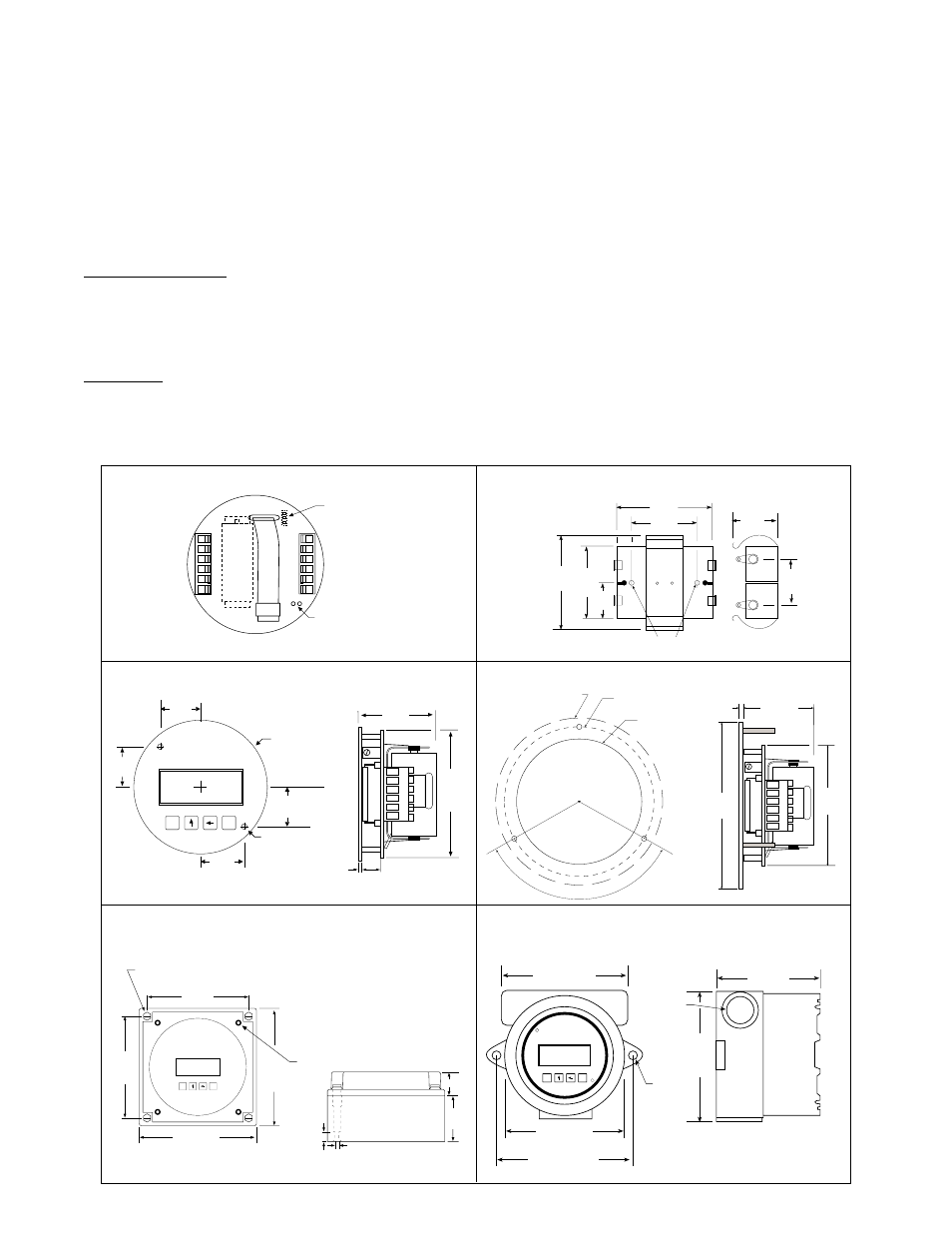
6 5 4 3 2 1
Rear View
Battery
Jumper Momentarily
To Initialize
7
8
9
10
11
12
BATPACK
Connector
BATPACK
2.093
(53)
1.75
(44.5)
1.625
(41)
.812
(20.6)
2.125
(54)
1.10
(28)
1.0
(25.4)
Mounting
Holes
Battery Installation and IT 300N Initialization:
All meter mounted IT 300N models are shipped with the batteries installed. When using external BATPACK,
mount within 12" and plug connector into 3 position square posts (see Fig 1). Polarity is not a concern because
center is common. The unit will have to be initialized and operating parameters entered.
CAUTION : All IT 300N models are provided with two or more sources of power. The power should not be
interrupted when changing batteries. For models with two batteries, change one battery at a time. If all power
sources are interrupted, information will be lost and the unit will have to be re-initialized as described below.
To install the battery, begin by locating the battery holder. The IT 300N-2, 3 and 5 require opening the enclosure
cover and removing the IT 300N to expose the battery holder.
The plus terminal of the battery is marked with a (+) symbol stamped into the battery holder. Be sure to install the
battery(ies) correctly.
To Initialize, Locate the “initialize” terminals on the IT 300N PCB (see Fig1). Using a small length of wire, tempo-
rarily jumper across the initialize terminals. The unit will respond by showing its software version number and then
illuminating the LCD display. See Programming Flowchart to setup desired operating parameters.
Fig 1