5 wiring, 6 terminal designations, All versions – Liquid Controls IT375 User Manual
Page 28: 20ma output version, Dc power version
Sponsler, Inc.
Model IT375
Installation Pg. 28
9.5 WIRING
When connecting the IT375 it is good practice to use shielded cable. The shield should be connected to earth at one end
of the cable. The other end of the shield should not be connected.
This wiring practice is mandatory in order to comply with the requirements for Electromagnetic Compatibility as per
EMC-Directive 89/336/EEC of the Council of the European Community
.
9.6 TERMINAL DESIGNATIONS
All versions
8
Pulse (+) / Coil Input
7
Pulse (-) / Coil Input
4-20mA and DC Versions
6
High Alarm (+) or Pulse Output (+)
5
High Alarm (-) or Pulse Output (-)
4
Low Alarm (+)
3
Low Alarm (-)
4-20mA Output Version
2
4-20mA (+)
1
4-20mA (-)
DC Power Version
2
DC Power (+) +9 to 28V
1
DC Power (-) 0V
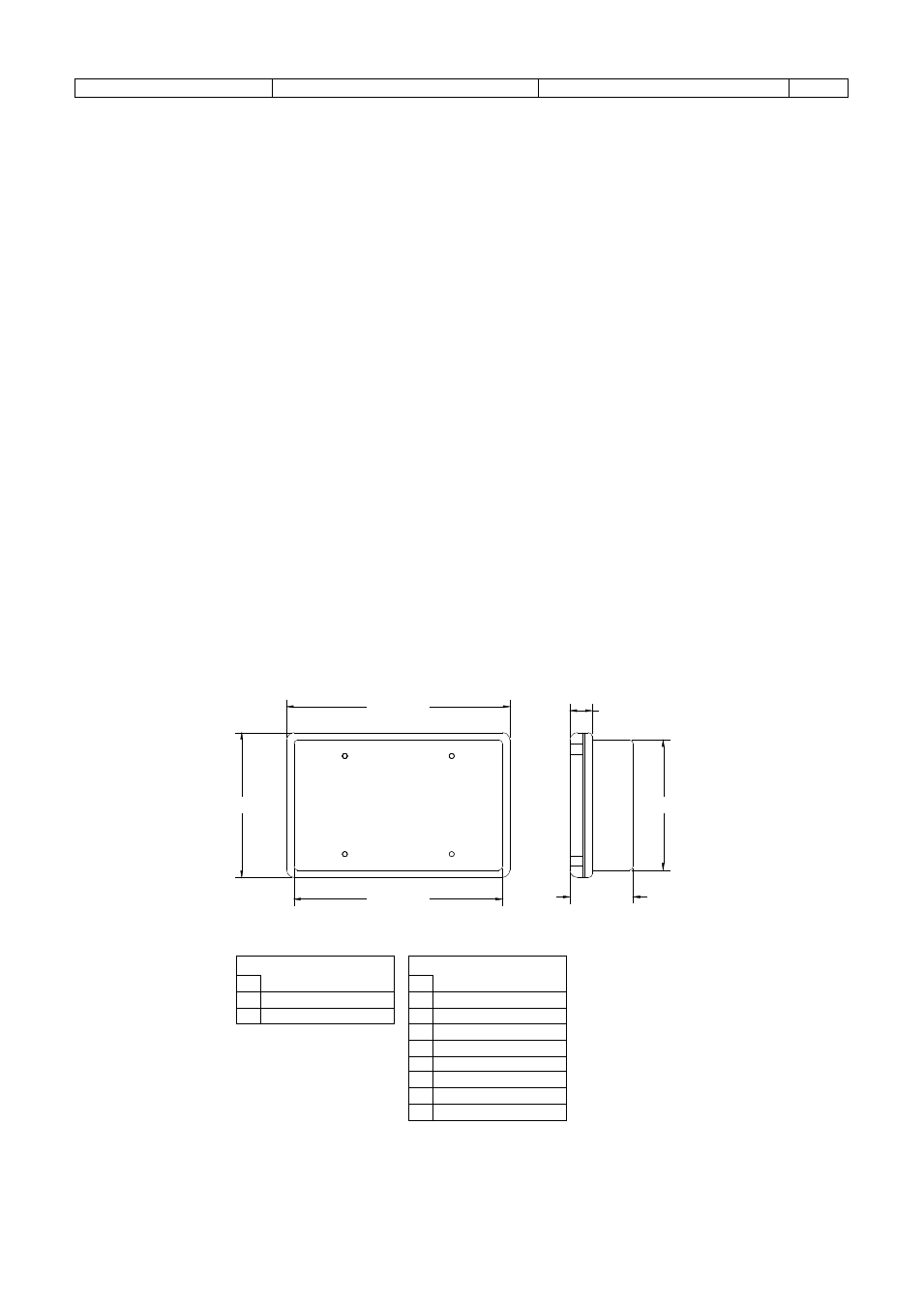
152mm (6.0")
98mm (3.9")
141mm (5.6")
87mm (3.5"
43mm (1.7")
16mm (0.6")
REAR VIEW
SIDE VIEW
Terminal Descriptions
Dimensional Drawing
All Versions
No.
7
8
Signal Input (-)
Signal Input (+)
4-20mA (-) or OVdc In
11
4-20mA (+) or +9-28Vdc In
2
4-20mA or DC Versions
No.
3
4
Low Alarm (-)
Low Alarm (+)
5
6
High Alarm (-) or Pulse (-)
High Alarm (+) or Pulse (+)