Pg.8, Disassembly procedure reassembly procedure – Liquid Controls Precision Turbine Flowmeters User Manual
Page 10
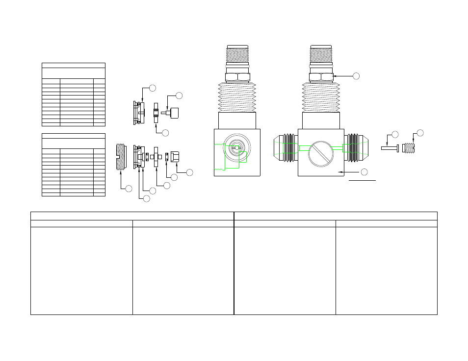
FIGURE 3: MF20-90 LO-FLO SERIES FLOWMETER
G
F
D-1
C-1
K
B
C-2
D-2
E
H
I
J
A
AN FLARE SHOWN
INTERNAL ASSEMBLY IS
TYPICAL FOR NPT, TUBE FITTING
HIGH PRESSURE, FNPT, & FLANGED
STANDARD LO-FLO SERIES
.
SLEEVED BEARING INTERNALS
1
1
1
1
1
1
1
1
PICKUP COIL
ORIFICE LOCK SCREW
ORIFICE
SHAFT
RETAINER
SCREW PLUG
HOUSING
J
I
H
E
B
A
QTY
DESCRIPTION
DESIGNATOR
ROTOR/BEARING ASSY.
D-2
C-2
K
O-RING****
1
**** CONSULT FACTORY FOR O-RING MATERIALS
AND INSTALLATION
1
O-RING****
K
C-1
D-1
ROTOR/SHAFT ASSY.
1
1
1
1
2
1
1
1
1
BALL BEARING INTERNALS
PICKUP COIL
ORIFICE LOCK SCREW
ORIFICE
BEARING CUP
BEARING
RETAINER
SCREW PLUG
HOUSING
J
I
H
G
F
B
A
QTY
DESCRIPTION
DESIGNATOR
This assembly references all Model Numbers
with Graphitar (GS), Teflon (TS), Carbide (CS),
This assembly references all Model Numbers
with Teflon Ball (TB), Metal Ball (MB) and
and Fluorosint (FS) sleeved bearing designators
Cryo Ball (CB) bearing designators.
DISASSEMBLY PROCEDURE
REASSEMBLY PROCEDURE
FOR BALL BEARING
FOR SLEEVED BEARING
FOR BALL BEARING
FOR SLEEVED BEARING
1. With a large screw driver, remove screw
plug.
2. Insert 4-40 screw into either of the tapped
holes on the face of the retainer and
extract from housing.
3. Remove bearings and rotor/shaft
assembly.
4. Review all parts for damage.
A. Check bearings thoroughly.
B. Check o-ring for cracks/nicks.
Replace if evident.
1. With a large screw driver, remove screw
plug.
2. Insert 4-40 screw into either of the tapped
holes on the face of the retainer and
extract from housing.
3. Remove rotor/bearing assembly.
4. Review all parts for damage.
A. Check bearing faces and bore
thoroughly.
B. Check o-ring for cracks/nicks
Replace if evident
NOTE: If any part appears damaged,
DO
NOT REASSEMBLE, call factory for
instructions.
1. Insert bearing into bearing cup.
2. Insert rotor/shaft assembly and bearing.
3. Insert retainer (with o-ring) and remove
4-40 screw.
4. Screw in screw plug.
NOTE: If any part appears damaged,
DO
NOT REASSEMBLE, call factory for
instructions.
1. Place rotor/bearing assembly on shaft.
2. Insert retainer (with o-ring) and remove
4-40 screw.
3. Screw in screw plug.
For liquid applications: Internals work best
when wet.
Pg.8