Maintenance, Turbine meter disassembly, Turbine meter assembly – Liquid Controls CIM100 User Manual
Page 9
MaIntenance
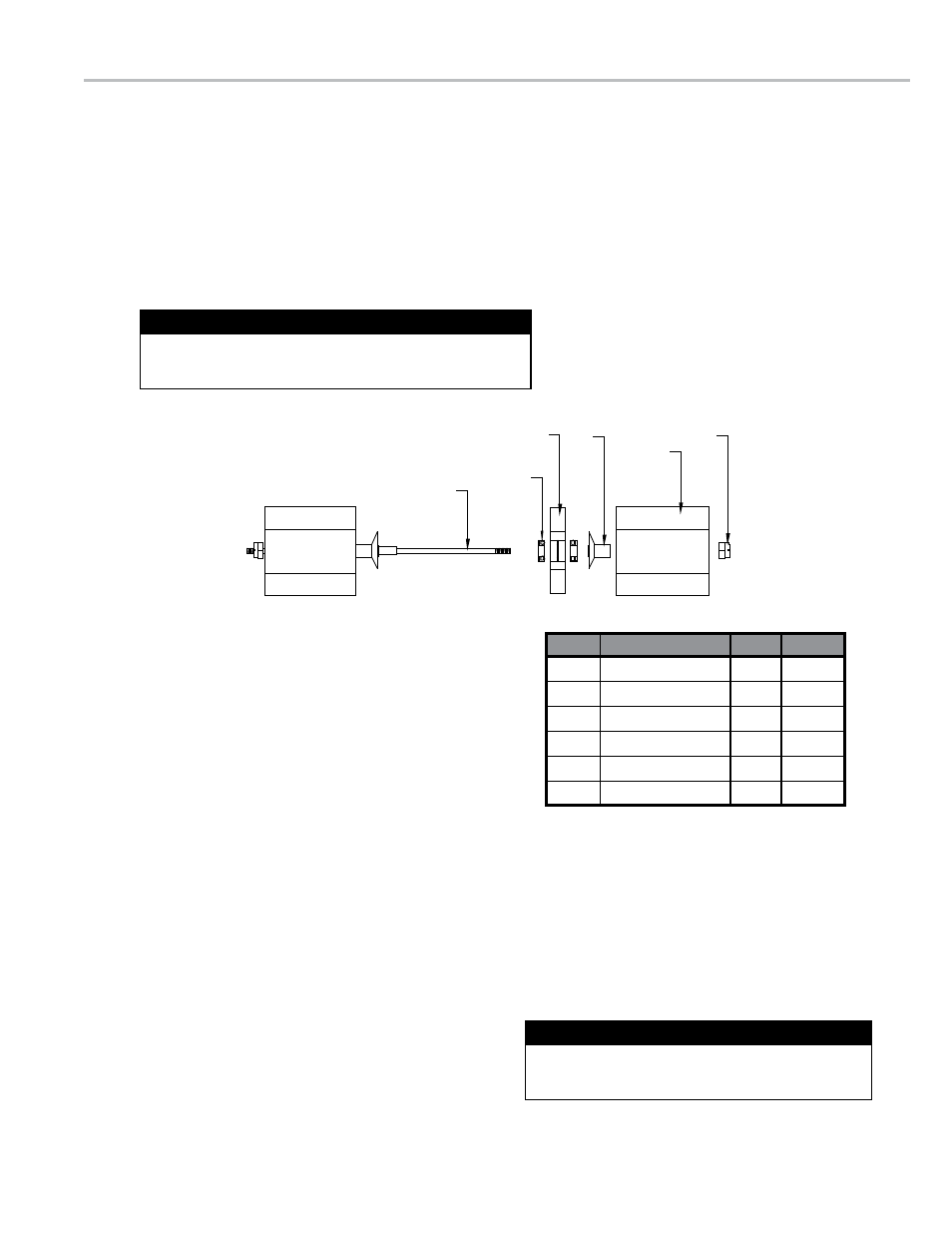
turbine Meter disassembly
1... Remove.lock.nut.from.shaft.end.on.the.inlet.side.
2... Insert.extraction.hook.into.inlet.clip.assembly.and.extract.with.a.parallel.pulling.motion.
3... Remove.cone,.bearings.and.rotor..
4.. Remove.outlet.clip.assembly.with.extraction.hook.as.directed.in.step.2..
Do not remove lock nut from outlet side clip
assembly..Leave.clip,.cone,.shaft.and.nut.assembled..(Refer.to.diagram)
1. Removal of internals should be performed in a clean area.
2. Ensure that internals are clean and dry before reassembling.
Assembly Notes
Item
DescrIptIon
Qty
part #
A
Bearing
2
PB-1
B
Rotor
1
PHL-1BB
C
Cone
2
CN1B-6
D
Clip Assy
2
CL1-6
E
Lock Nut
2
HS005
F
Shaft
1
SH1-6
turbine Meter assembly
1... Place.meter.on.table.vertically,.outlet.side.up.
2... Insert.outlet.clip/cone/shaft/nut.assembly.into.the.housing..Push.down.until.the.assembly.is.seated.against.the.step.in.the.
housing..Clip.bundle.diameter.may.need.to.be.clamped.for.easier.insertion.
3... Flip.meter.so.the.inlet.side.is.up..Insert.bearing,.rotor,.bearing,.then.cone..
4... Insert.inlet.clip.assembly.
5... Screw.on.lock.nut.snug.against.inlet.clip
If any part appears damaged “DO NOT REASSEMBLE”.
Call factory for instructions.
Damaged Parts
F
A
B
C
D
E
9