Montage / installation du socle télé, Attaching arms to the back of the flat panel tv – Level Mount ELTVS60 User Manual
Page 10
10
www.levelmount.com
1-888-229-1459
EU: +44 844 5672657
UK: 0844 5672657
©2011 Level Mount - Patents Pending
Step 1 – Selecting the Correct Hardware Based on TV
Back
Before beginning the installation, determine if the TV has a flat back or a
recessed back as shown in Figure 1. If you have a recessed back TV you
may need to use the spacers (Bag 5) as shown in Figure 4 or Figure 6. The
spacer is used to fill the recessed area of the TV so that the TV Bracket is
fully supported and flush with the back of the TV.
Flat Back
Recessed Back
Figure 1
Step 2 - Extension Arm Installation (if needed)
If the holes in the Fixed or Tilt Arms do not line up with the holes in back of
the TV, do not drill. Instead, follow these instructions for the Extension Arm
Installation. Otherwise, skip to Step 3.
Note: When using the Fixed Arms, the Extension Arms can be used for
TVs with VESA vertical hole placement that is greater than 370mm;
and when using the Tilt Arms, the Extension Arms can be used
for TVs with a VESA vertical hole placement that is greater than
500mm. Your TV manual/product labels should specify the VESA
hole spacing.
Step 2b - Completed Extension Arm Attachment
All 4 Extension Arms should be attached in the same manner. When
completed, your Fixed or Tilt Arms, with the Extension Arms attached, should
appear as shown in the photo in Figure 3.
Step 2a - Attaching Extension Arms to Fixed or Tilt
Arms
Attach the Extension Arms to the Fixed or Tilt Arms using the following
hardware as shown in Figure 2:
• Bolts M5 (Bag 7)
• Lock Washer M5 (Bag 7)
• Extension
Arm
• Fixed or Tilt Arm
• Nut M5 (Bag 7)
Adjust the screws in Figure 2 to move the extension arms to align with the
holes on the back of the TV.
Figure 2
Extension Arm
Fixed/Tilt Arm
M5 Lock Washer
M5 Lock Washer
M5 Hex Nut
M5 Hex Nut
M5 Bolt
M5 Bolt
Figure 3
Lower Extension Arms
Upper Extension Arms
Fixed or Tilt
Arms
Fixed or Tilt
Arms
Attaching Arms to the Back of the Flat Panel TV
39
www.levelmount.com
1-888-229-1459
EU: +44 844 5672657
UK: 0844 5672657
©2011 Level Mount - Patents Pending
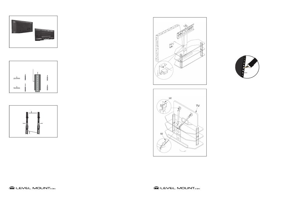
Étape 22 – Pour fixer le socle télé au support mural (U) (il faut deux
personnes), soulever le socle télé de manière à ce que le support
plat (T) soit au niveau du centre du support mural (U). Rapprocher
doucement le socle télé du mur de façon à ce que le support plat (T)
flotte au-dessus du rebord inférieur du support mural (U). Accrocher
en douceur le support plat dans l’encoche du support mural (U) et
abaisser jusqu’à ce que le socle télé repose sur le sol.
Étape 23 – POUR ELTVS55
, ELTVS60
Pour sécuriser le téléviseur
au socle télé, fixer les supports télé (U2) à l’arrière du téléviseur
à écran plat à l’aide des les boulons et de rondelles correcte qui
correspondent à la télévision.
Remarque : Les fabricants percent des trous à l’arrière des
téléviseurs afin qu’ils puissent être fixés à des éléments de fixation
murale.
Étape 24 – Engager les fermoirs des sangles de sécurité (S2) dans
les trous en haut du support plat (T). Raccorder les autres extrémités
des sangles de sécurité (S2) aux trous des supports télé (U2).
Montage / Installation du Socle télé
Figure 8
Figure 9
Note - Si la position souhaitée pour le téléviseur n'est pas situé
directement en face d'un montant du mur, fi xez le support mural (U)
au
Attache cloison sèche
le plus proche dans le voisinage du Socle
télé. Une fois que la télévision est monté sur le stand (instructions
commencent à la page 40), clip une extrémité de chaque sangle
de sécurité (S2) dans un trou dans le support mural (U) et les autres
extrémités dans l'une des trous dans les bras qui sera attaché à la TV
(fi gure 8A).
Figure 8A
Arrière
de TV
Bras fixe/
rotatif