Hardware installation, Installing/removing receiver modules, Installing the vr field system – Lectrosonics VRFIELD (Narrowband) User Manual
Page 8: Installing receiver modules, Removing receiver modules
VR Field
Hardware Installation
Installing/Removing Receiver Modules
Up to six Receiver Modules can be installed in a VRF
chassis. These modules may be installed at the factory
or added later.
Although the VR Field System is quite flexible, any com
bination of Receiver Modules installed must be within
the frequency block range of the VRF chassis. The
frequency block range of the VRF chassis is displayed
during the PowerUp Sequence.
Frequency.Block.Range
Installing Receiver Modules
1. Ensure the VR Field System is turned off and the
power source has been disconnected. Slide the
Receiver Module Connector firmly onto the Receiv
er Module Tab.
Caution: Do not force the Receiver Module
onto the Receiver Module Tab. If the module
does not seat properly, look to see if its
position is a little off. Excessive force may
damage the module’s connector or the
Receiver Module Tab.
2. Install a Receiver Module Retaining Clip between
the rear of the Receiver Module and the Module
Tab. Ensure this clip is firmly snapped into place.
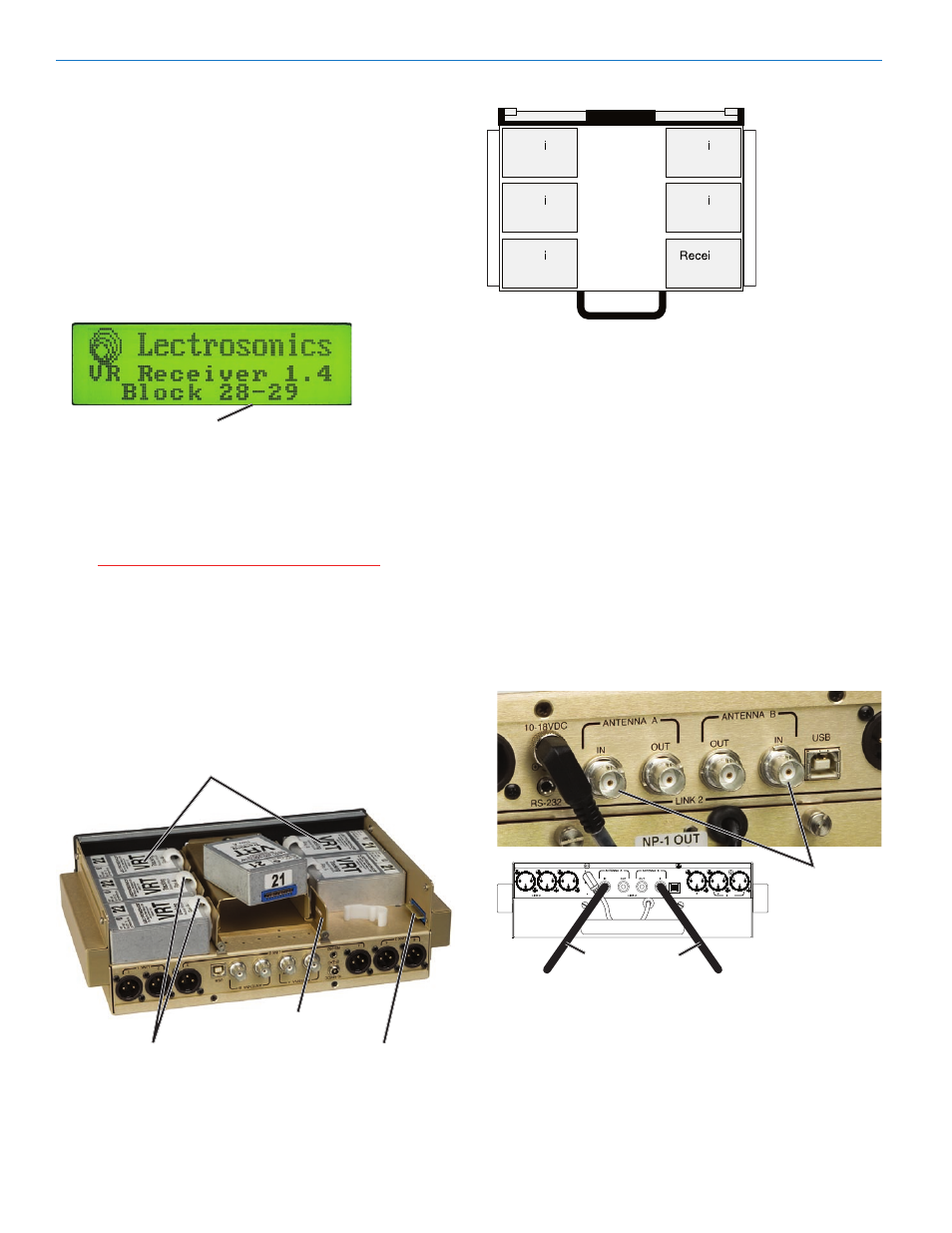
Receiver.Modules
Receiver.Module.Tabs
Receiver.Module.
Receiver.Module.
Retaining.Clips
Connectors
Bottom View of the Chassis
VRF.Front.Panel
VRF.Rear.Panel
Removing Receiver Modules
1. Ensure the VR Field System is turned off and the
power source has been disconnected.
2. Remove the Receiver Module in the reverse order
of installation, i.e., remove the Receiver Module Re
taining Clip, then slide the module off the Receiver
Module Tab and remove it from the VRF chassis.
Installing the VR Field System
The VR Field Receiver is designed for portable use, as
in a bag system.
1. Position the unit for easy access to the panel con
trols and connections. There are no special ventila
tion requirements.
2. Connect the antennas (or antenna cables if remote
antennas are being used) to the antenna input con
nectors on the rear panel of the VRF.
Coaxial.Cables
Antenna
Inputs
3. For multiple unit installations, connect coaxial patch
cables from the Antenna A and B OUT jacks on the
rear panel of the first unit to the Antenna A and B IN
jacks on the second unit. An additional unit can be
connected to the second unit in the same manner.
Note: All units connected in this manner must be on the same
frequency block.
LECTROSONICS, INC.