Setup and operation using lcd, Resetting to factory defaults, System setup checklist – Lectrosonics VRFIELD (Narrowband) User Manual
Page 10: Locate clear channels
VR Field
Setup and Operation Using LCD
Use the following procedures to setup and operate the
VR Field System using the front panel LCD, pushbut
tons and controls.
These procedures assume there is at least one receiver
module installed and that receiver module is installed in
Slot 1. If there is at least one receiver module installed,
but it is not in Slot 1, then use the lowest numbered
slot where a receiver module is installed as the starting
point for the following procedures.
For detailed information on the functions and setup
screens used for these procedures, refer to the VR
Field System Reference Manual.
Resetting to Factory Defaults
Resetting to Factory Defaults can be of great benefit
when everything is going wrong and it’s time to start
back at the beginning. This is done by powering off the
VR Field System, then pressing and holding Receiver
Select buttons 5 and 6 while powering up the system.
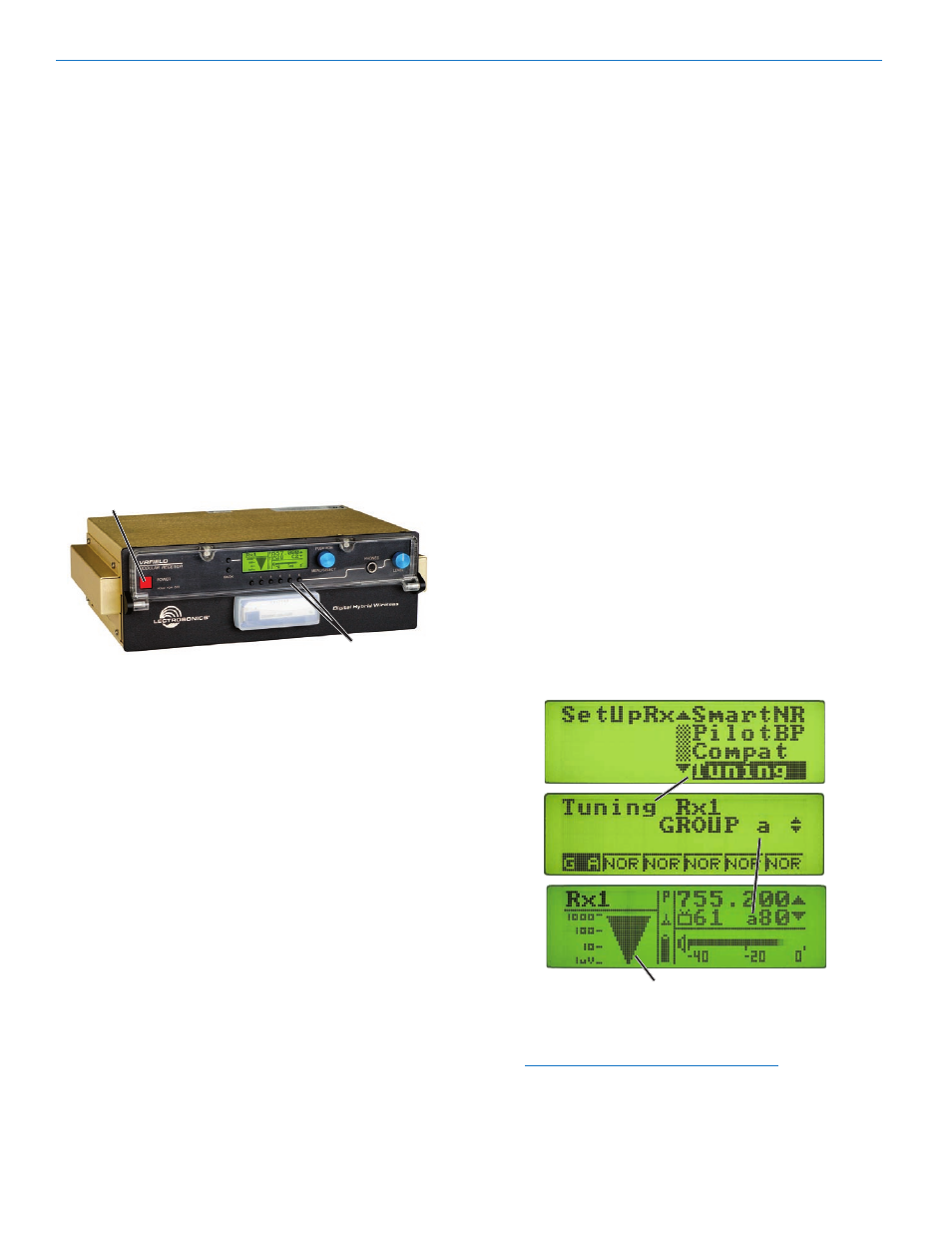
POWER.Switch
Receiver.Select.
Buttons.5.and.6
The Factory Default Settings are:
SetUpRx. Level
+00 dBu
Phase
NORMAL
TxBatt
9V ALK
SmartNR
NORMAL
PilotBP
NORMAL
Compat
Dig. Hybrid
Tuning
NORMAL MODE
DivMode
Switched
LockSet
Lockset
NOT LOCKED
System Setup Checklist
The following steps are needed to set up the system.
1. Locate Clear Channels
2. Set Diversity Modes
3. Set Compat Mode, Audio Levels, Battery Status
Monitoring and Noise Reduction Mode
4. Set Transmitters to Match Receiver Frequencies
5. Adjust Audio Output Levels
6. Conduct a Walk Test
Locate Clear Channels
Finding clear operating frequencies for multiple channel
receivers, such as the VR Field System, is a bit more
complicated than single channel receivers. This is due
to intermodulation, or interference from other transmit
ters. Minimizing this problem is critical to ensure quality
audio. Regardless of which procedure is used to locate
a clear channel, the clear channels discovered need
to be compared with those listed on the Compatible
Frequency Chart to ensure minimal intermodulation
problems. (See Frequency Coordination.)
Using a Tuning Group to Locate Clear Frequencies
1. Turn all transmitters OFF. Then press Receiver
Select Button “1” (below the LCD) to access the
receiver detail screen.
2. Press the MENU/SELECT control, the rotate the
knob to select Tuning. Press the knob again to enter
the Tuning Setup screen. Rotate the knob while
observing the LCD, then select “GROUP a.” The
letters “G A” will appear in the small box in the lower
left part of the LCD. Press the BACK button twice to
return to the receiver detail screen.
5. Observe the RF signal strength meter on the LCD
and rotate the MENU/SELECT control through the
eight preselected frequencies and find one where
no RF signal is present. Any signal displayed
indicates RF Interference. No RF signal strength
indicates a clear channel.
6. If no clear frequency can be found, try using
“GROUP b” and repeat the procedure above.
RF.Signal.Strength.Meter.
(strong.signal.being.received)
7. Continue this procedure for the other receivers.
Leave all transmitters OFF.
NOTE: Review the chapter on Frequency
Coordination near the back of this manual for more
details on compatibility between frequency groups.
LECTROSONICS, INC.
10