Help menu, Client area, Popup menu – Lectrosonics VRFIELD (Narrowband) User Manual
Page 20: Set up vr, Spectrum scan
VR Field
Help Menu
Help provides access to the online Help file, VRpanel
demonstration mode and an About Box featuring the
VRpanel’s current version number.
The Help file offers users detailed information on the
setup and operation of the VR Field System.
Client Area
The Client Area holds one or more panes, each graphi
cally representing one VR system. Each pane, in turn,
holds from one to six plug-in receiver modules (receiver
modules). An information line at the top of each pane
identifies the VR System USB Identification and fre
quency block range.
VR.System.
Information
Installed.
Reciever.
Modules.(Plug
in.Receivers)
Popup Menu
Because VRpanel is capable of monitoring and control
ling more than one VR system, none of the commands
available through the Menu Bar are available for individ
ual systems. To work directly with a specific VR system,
right-click anywhere in its pane to open a popup menu.
This menu includes commands for configuring the VRs
receiver modules, running the spectrum scanner, real-
time recording of a walk test, resetting the current VR
system back to factory defaults or deleting the current
VR system from VRpanel.
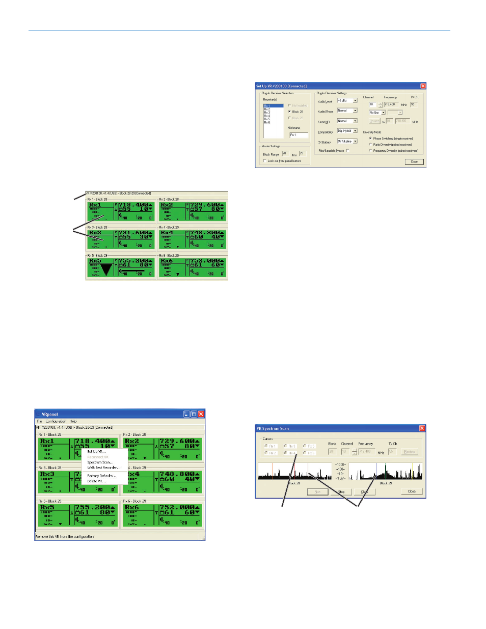
Set Up VR
The Set Up VR dialog is used to control all the stored
settings for the currently selected VR system.
This dialog allows for convenient selection and setup of
all installed receiver modules in the currently selected
VR system and global settings for the VRF. It consists
of three sections: Plug-In Receiver Selection, Plug-In
Receiver Settings and Master Settings. Changes to any
of the Plug-In Receiver Settings are done in real time.
Spectrum Scan
There are three sections to the Spectrum Scan dialog
box: cursors, spectrum scanner and command buttons.
Cursors controls cursor selection (and thus the tuning
of the selected receiver module). The cursor for the
selected receiver module appears as a dashed line in
the spectrum scanning section and its frequency detail
is displayed to the right of the cursor radio buttons.
This information includes the frequency block number,
transmitter frequency select switch settings, operating
frequency and TV channel.
When this dialog initially appears, a cursor will be
located at the set operating frequency for each installed
receiver module, or receiver module pair. Clicking
Run
starts the spectrum scanner. A separate cursor moves
to identify the real-time location of the scan within each
frequency block.
All.Receivers.in.Switched.Diversity.Mode
Cursor.Select
Receiver.Module.
Frequency.Locations.
Moving any of the cursors automatically changes the
operating frequency for the corresponding Receiver
Module, or module pair depending on the diversity
mode.
0
LECTROSONICS, INC.