Setting audio output levels, Setting transmitter battery status monitoring – Lectrosonics VRFIELD (Narrowband) User Manual
Page 13
Digital Hybrid Wireless™ Modular Receiver System
Setting Audio Output Levels
This sets the audio output level at the Audio Output
XLR Jacks. The front panel LEVEL control is only for
setting the audio output level in the PHONES jack.
Note: In OptiBlend (ratio diversity) and Frequency
Diversity modes, the Receiver Modules are paired
(1-2, 3-4, 5-6). Setting the audio level output on
one of the receivers in the pair, sets the audio
output to the same level on its compliment.
1. Set the audio input level for any equipment con
nected to the VR Field System’s Audio Output XLR
Jacks to minimum. (This is to avoid annoying or
loud noises during setup.
2. Set the audio input level for the equipment con
nected to the XLR jack associated with Receiver
Module 1 to the equipment manufacturer’s recom
mendations.
3. Navigate to the Level Setup Screen, then use the
Receiver Select buttons to select receiver module 1
and set the audio output level to 0 dBu.
Note: The 0 dBu setting is a starting point. The
key is to provide as high a level signal as possible
without overdriving the input to external equipment
connected to the XLR Jack associated with the
receiver module, or receiver module pair. This
will minimize possible noise from the cables.
Generally speaking, the higher the output level in
the cables, the less you need to worry about cable
noise.
4
. Press Function to turn on the 1 kHz Tone (the Tone
indicator will reverse, or go black with white letters)
and rotate the MENU/SELECT control to optimize
the input to the external equipment.
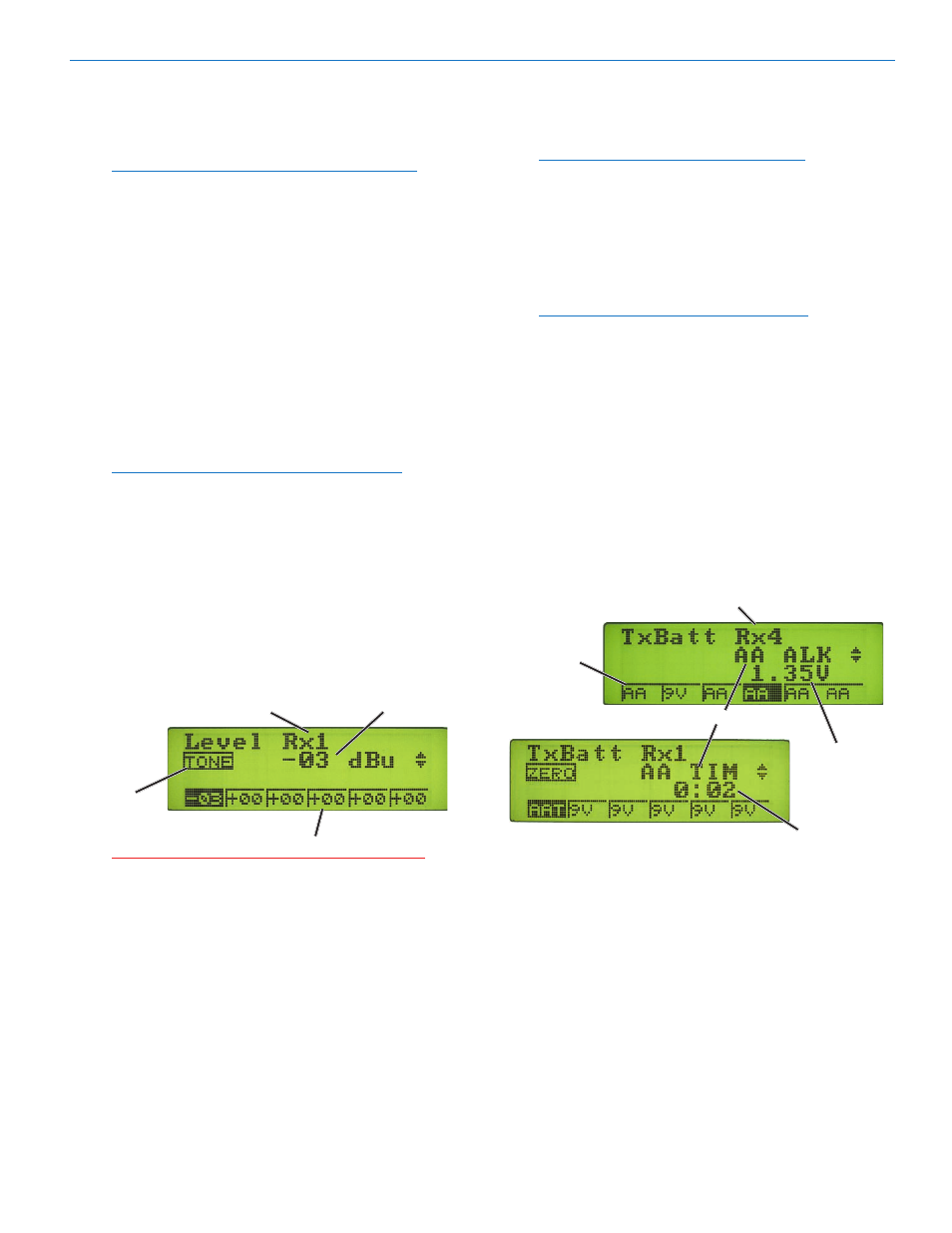
Output.Level
Selected.Receiver
Tone.On/Off.
Indicator.
(Shown.in.Off.
position.)
Receiver.Modules
Caution: The 1 kHz reference tone is equivalent
to full modulation at the transmitter, i.e., it is
loud.
6. Repeat Steps 2 through 4 until the audio output
level on all receiver modules has been set.
Setting Transmitter Battery Status Monitoring
1. Determine the types of transmitters being used and
the types of batteries installed in the transmitters.
Note: In 200 Series and Digital Hybrid (400
Series) compatibility modes, battery telemetry is
available and all TxBatt modes are valid. In all
other compatibility modes, only the battery timer
modes are valid. (See TxBatt Setup Screen in VR
Field System Reference Manual.)
2. Access the TxBatt Setup Screen.
3. Select Receiver Module 1.
Note: If the selected receiver module is part
of a ratio diversity pair, then setting the TxBatt
type monitoring for one receiver in the pair
automatically sets the TxBatt type monitoring
for the other receiver in the pair. If the selected
receiver module is part of a frequency diversity
pair, then each receiver in the pair is matched to a
different transmitter so the TxBatt type monitoring
setting is set independently of the other receiver
module in the diversity pair.
4. Rotate the MENU/SELECT control to display the
desired transmitter battery type, or timer for the
style of battery used by the transmitter (9V or AA).
(See TxBatt Setup Screen in VR Field System Ref
erence Manual.)
5. Repeat Steps 3 and 4 for each receiver module.
Selected.Receiver
Receiver.
Modules
Monitoring.Mode
Elapsed.Time
Current.
Transmitter.
Battery.Voltage
Rio Rancho, NM
1