Rear panel, Rear panel features, Power input jack – Lectrosonics VRFIELD (Narrowband) User Manual
Page 7: Receiver modules, Xlr audio output jacks, Rs-232 port, Antenna input jacks, Antenna output jacks, Usb port
XLR.Audio.Output.Jack.
XLR.Audio.Output..Jack.
Antenna.(B).Output
Digital Hybrid Wireless™ Modular Receiver System
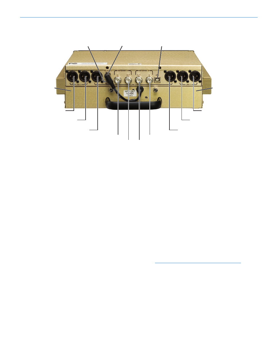
Rear Panel
RS-232.Port
Power.Input.Jack
USB.Port
Receiver.
Modules.4-6
(Inside)
(Receiver.6)
XLR.Audio.Output.Jack.
(Receiver.5)
XLR.Audio.Output.Jack.
(Receiver.4)
Antenna.(A).Input
Antenna.(A).Output
Rear Panel Features
The rear panel provides six balanced XLR audio out
puts, two 50 Ohm BNC antenna inputs, two 50 Ohm
BNC antenna outputs from an internal multicoupler, a
power jack with a locking connector, and USB and RS
232 serial ports.
Power Input Jack
The power input jack accepts +10 VDC to +18 VDC
(center pin is positive and sleeve is ground). The input
is diode protected to prevent damage if the power is
accidentally applied with reversed polarity. The unit will
not operate until the correct polarity is restored.
Receiver Modules
Up to six receiver modules in two rows of three can be
installed in each VRF. Spring loaded Receiver Module
Retainer Clips ensure module connections are main
tained during transport and installation.
XLR Audio Output Jacks
Six balanced audio output jacks using standard XLR
connectors are provided to connect the VR Field
System to external equipment. The default value for
receiver audio output is “in phase” in regard to the audio
signal from the transmitter. This can be reversed using
the Phase Setup Screen. (See VR Menu Functions,
Phase.)
Receiver.
Modules.1-3
(Inside)
(Receiver.1)
XLR.Audio.Output.Jack.
(Receiver.2)
XLR.Audio.Output.Jack.
(Receiver.3)
Antenna.(B).Input
RS-232 Port
A serial RS-232 interface is provided for setup and
control of the VR Field System from computers or other
devices using industry standard RS-232 communication
links.
Antenna Input Jacks
Two BNC input connectors are provided for right-angle
whip antennas, cables from remote antennas, or cables
from another VR Field. An internal mulitcoupler en
sures the RF is applied equally to all installed Receiver
Modules and also to the Antenna Output Jacks.
Antenna Output Jacks
Two pairs of 50 Ohm BNC output jacks provide zero-
gain antenna “loop-throughs” for an additional receivers,
allowing convenient expansion without the need for an
external RF multicoupler or additional antenna systems.
Note: VR Field Systems can be looped together
successfully only when they cover the same
frequency block range. Units outside of the
frequency block range will experience substantial
signal loss and very short operating range.
USB Port
Standard USB Version 1.1 connector for setup and
control from computer systems (Windows
®
2000 or XP)
with a USB interface.
Rio Rancho, NM