Safety considerations, Provision for cooling, Symbols used – Laurel Electronics LTSE6 - Manual User Manual
Page 4: Caution (refer to accompanying documents), Caution, risk of electric shock, Earth (ground) terminal, Both direct and alternating current
-
- 4 -
5. SAFETY CONSIDERATIONS
Warning: Use of this transmitter in a manner other than specified may impair the protection of
the device and subject the user to a hazard. Visually inspect the unit for signs of damage. If the unit is
damaged, do not attempt to operate.
Caution:
• This unit may be powered with AC (mains) from 85-264 Vac or 90-300 Vdc with the high voltage
power supply option, 12-30 Vac or 10-48 Vdc with the low voltage power supply option. The latter
allows Power over Ethernet (PoE) to be selected by jumpers. Verify that the proper power option
is installed for the power to be used. This transmitter has no AC (mains) switch. It will be in
operation as soon as power is applied.
• The 85-264 Vac or 90-300 Vdc mains connector (P1 Pins 1-3) is colored green to differentiate it
from other input and output connectors. The 12-30 Vac or 10-48 Vdc mains connector is colored
black.
• To avoid dangers of electrocution and/or short circuit, do not attempt to open the case while the
unit is under power. However, signal wiring changes external to the case can be made safely while
the unit is under power.
• To prevent electrical or fire hazard, do not expose the transmitter to excessive moisture.
• Do not operate the transmitter in the presence of flammable gases or fumes. Such an environment
constitutes an explosion hazard.
• Secure the transmitter to a 35 mm DIN rail.
Symbols used:
Caution (refer to accompanying
documents)
Caution, risk of electric shock.
Equipment protected throughout
by double insulation or reinforced
insulation.
Earth (ground) terminal.
Both direct and alternating current.
Operating environment:
• Class II (double insulated) equipment
designed for use in Pollution degree 2.
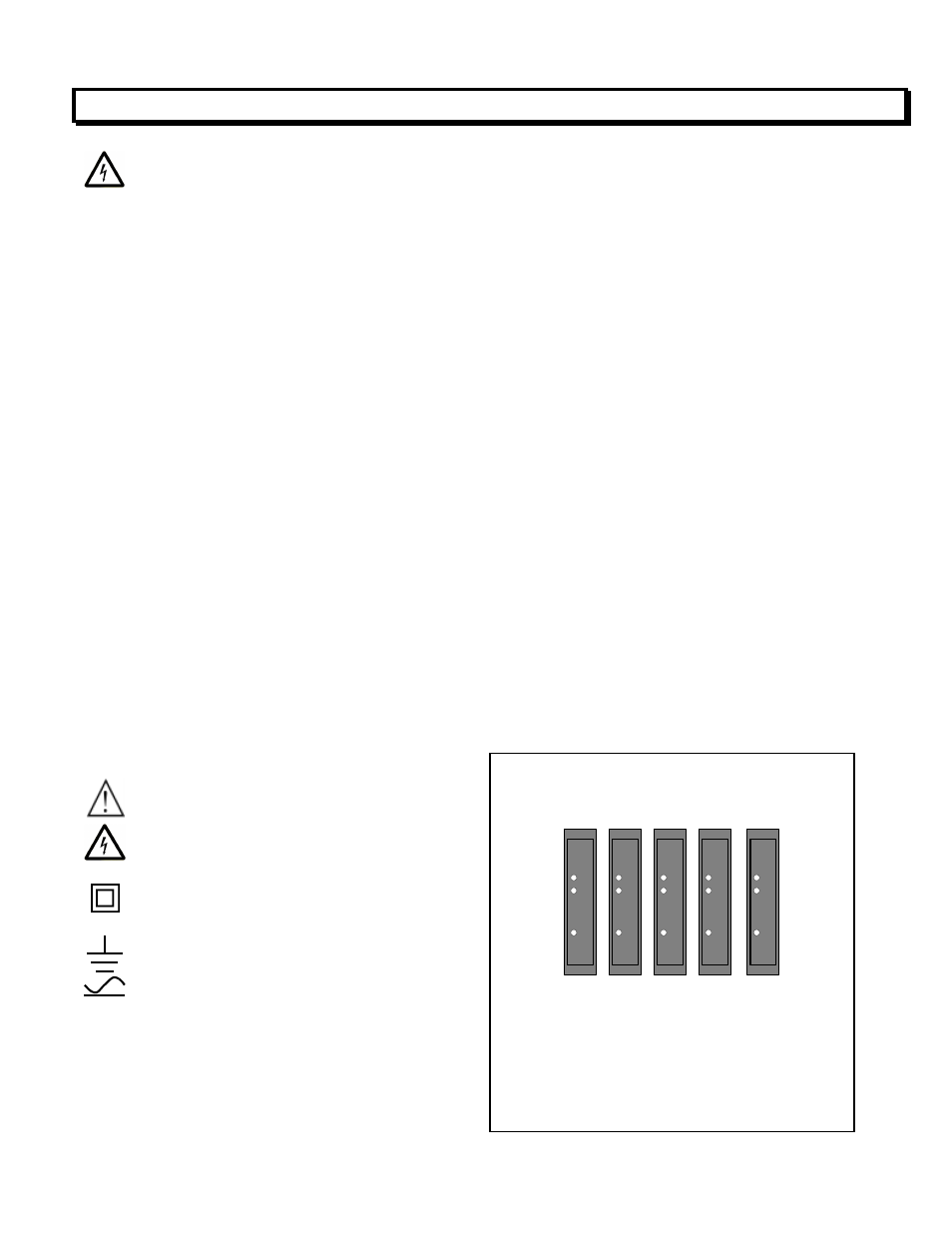
PROVISION FOR COOLING
AL 1
AL 2
RESET
POWER
AL 1
AL 2
RESET
POWER
AL 1
AL 2
RESET
POWER
AL 1
AL 2
RESET
POWER
AL 1
AL 2
RESET
POWER
To avoid overheating, mount transmitters
with ventilation holes at top and bottom.
Leave a minimum of 6 mm (1/4”) between
transmitters, or force air with a fan.