Laurel Electronics LTSE6 - Manual User Manual
Page 18
-
- 18 -
4. COMMUNICATIONS SETUP
Parameters selectable via Instrument Setup software, distributed on CD ROM:
Serial Protocol ...............................Custom ASCII, Modbus RTU, Modbus ASCII
Modbus ASCII Gap Timeout...........1 sec, 3 sec, 5 sec, 10 sec
Baud Rate.......................................300, 600, 1200, 2400, 4800, 9600, 19200
Parity .............................................No parity, odd parity, even parity
Device Address .............................0 to 247
5. SUPPORTED FUNCTION CODES
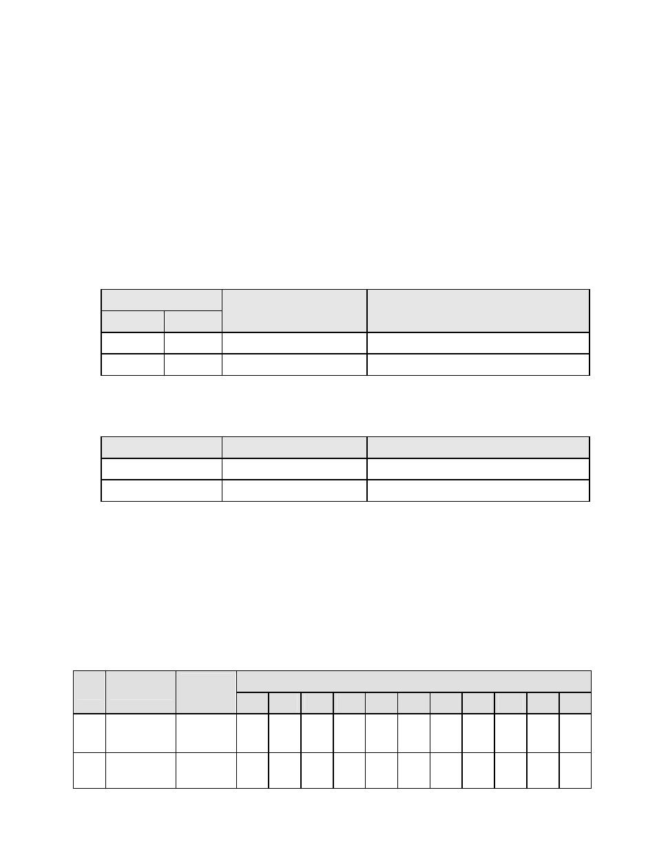
FC10: Write Multiple Registers (FC10 = 16 dec)
Writes internal registers containing input data for analog output and relays.
Register Address
Dec
Hex
Data Type
Destination
107
006B
Hi Word Hex Value
Hi Word Applied to Item3
108
006C
Lo Word Hex Value
Lo Word Applied to Item3
FC05: Write Single Coil
Action command to transmitter
Output Address
Output Value
Action Command
00 01
FF 00
Transmitter Reset (No Response)
00 03
FF 00
Latched Alarm Reset
6. MESSAGE FORMATTING
MA = Device Address DD = Data (Hex)
CL = CRC Lo Byte
FC = Function Code WW = Data (On/Off)
CH = CRC Hi Byte
RA = Register Address SF = Sub-Function
CR = Carriage Return
NR = Number of Registers EC = Error Code
LF = Line Feed
NB = Number of bytes LRC = ASCII Checksum
Modbus RTU Format
Byte Number
FC
Action
> 3.5
Char
1
2
3
4
5
6
7
8
9
10
11
05
05
Request
Response
NoTx
NoTx
MA
MA
FC
FC
RA
RA
RA
RA
WW
WW
WW
WW
CL
CL
CH
CH
10
10
Request
Response
NoTx
NoTx
MA
MA
FC
FC
RA
RA
RA
RA
NR
NR
NR
NR
NB
CL
DD*
CH
DD* CL
CH