5 master / slave wiring, 1 operator interface – Controlled Products Systems Group 9050-080 User Manual
Page 29
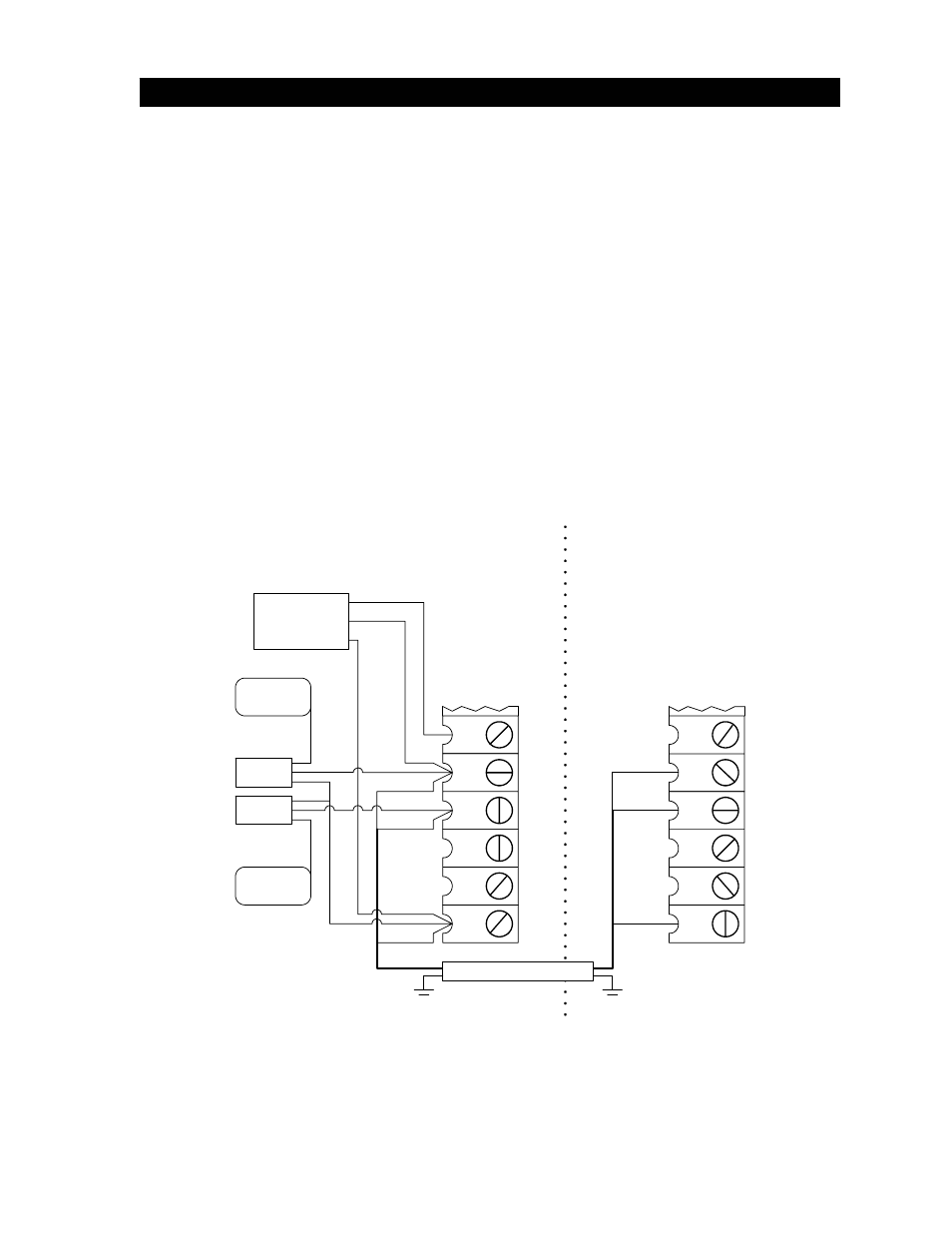
2.5 MASTER / SLAVE WIRING
2.5.1 OPERATOR
INTERFACE
The interface wiring between the two operators requires four (3) 18 AWG wires for control plus two
(2) additional 18 AWG wires for secondary entrapment protection device connection. Each operator
must be connected to it's own power source as described in section 2.2.
IMPORTANT! Plug-in loop detectors cannot be used in master / slave applications with these
operators. Use external detectors that have a normally open (N.O.) dry contact as a signal
device.
1. Connect the master / slave wiring (terminals 8, 9, 12) as shown in figure 29. Be sure that
power to both operators is OFF.
2. Connect the common (C) and normally open (N.O.) relay contacts from the OPEN loop
detector to terminals 8 and 12.
3. Connect the radio receiver as shown. Note that the relay contact from the radio receiver
connects to terminal 8.
4. Connect any other OPEN devices to terminals 8 and 12. Connect standard external
REVERSING devices to terminals 9 and 12. See section 2.5.2 for secondary entrapment
protection device wiring for master / slave operators.
11
9
10
12
M
a
ste
r Operator
Sla
v
e
Oper
a
tor
Connect Chassis Ground To
Chassis Ground (Green Wire)
7
8
Common
Relay
Power
Open Loop
Reverse Loop(s)
Master / Slave Conduit
Orange
Brown
Yellow
Yellow
Orange
Loop
Detector
Loop
Detector
Brown
Radio
Receiver
10
12
8
9
11
7
Figure 29
19